White Paper: Testing and Stabilizing Feedback Loops
Download now.
WhITE PAPER
Testing and Stabilizing Feedback Loops in Today's Power Supplies
Feedback loops aren't what they used to be. Gone are the days of a single feedback path, an external or discreet error amplifier, and a direct connection from output to input. Gone also are the days of voltage mode control, even though it is a better choice in some applications. The majority of power supplies manufactured today throughout the world use a similar topology. Multiple outputs with coupled inductors each feed the common summing node of a TL431 "programmable zener" error amplifier. The TL431 drives the diode portion of an opto-coupler, with the transistor portion on the primary (line) side of the isolation barrier controlling the operating point of a current-mode control chip. The internal error amplifier on the current-mode control chip may or may not be used as a buffer and/or gain stage. Learn more by downloading our white paper that details practical tips in dealing with the problems made by modern topologies.
In this white paper, you'll learn:

• How It Works
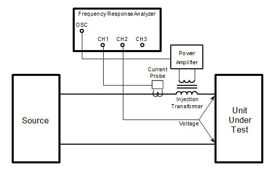
• Measuring Voltage Loop Gain
• Measuring Current Loop Gain
• Improving the Voltage Loop
• Dealing with Multiple Outputs and Coupled Inductors
Download this white paper to learn how to test and stabilize feedback loops in modern power supplies. Complete the form on the right to gain access.
Download White Paper
Fill out this form to gain access to this white paper.
About Venable
Venable provides scalable energy storage and power systems test solutions for precise voltage, current, and frequency measurements, partnering with engineers to ensure battery and power systems around the world will meet stringent field performance demands.
Recent news
Subscribe
Subscribe to our blog to receive emails and updates on scalable power and energy systems test solutions from Venable Instruments.
Contact us
8656 SH 71 West
Cuesta Centre, Building E
Austin, TX 78735
Office: 512-949-3100
Fax: 512-949-3151


