White Paper: Testing Power Correction
Download the white paper today.
WhITE PAPER
Testing Power Factor Correction Circuits for Stability
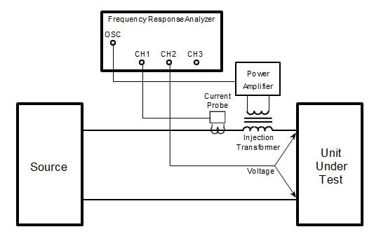
 Power factor correction has become an increasingly necessary feature in new power supply designs. In a power factor correction circuit, there are two feedback control loops. One loop operates by using the input voltage as a reference to control the input current. This loop is fast and makes the input current instantaneously proportional to input voltage as it would be with a resistive load. A second loop, which is much slower, controls the constant of proportionality to make the average current correct to keep the output voltage of the power factor correction circuit constant. Testing the slow loop for stability is easy with the proper equipment, but testing the faster loop is much more difficult. The operating point of the faster loop is dynamically changing from near zero to the peak value of the input current.
Download this white paper to learn tips and techniques necessary to measure the stability of each of these loops and specifies necessary equipment and procedures to perform these tests. Complete the form on the right to gain access.
Download White Paper
Fill out this form to gain access to this white paper.
About Venable
Venable provides scalable energy storage and power systems test solutions for precise voltage, current, and frequency measurements, partnering with engineers to ensure battery and power systems around the world will meet stringent field performance demands.
Recent news
Subscribe
Subscribe to our blog to receive emails and updates on scalable power and energy systems test solutions from Venable Instruments.
Contact us
Venable Instruments
8656 SH 71 West
Cuesta Centre, Building E
Austin, TX 78735
Office: 512-949-3100
Fax: 512-949-3151


