Bode Box Verification Test
The Bode Box test is performed to verify that the injection transformer is working correctly using a Venable Frequency Response Analyzer FRA. It is basically a transfer function measurement that verifies that the 10:1 step down ratio and frequency bandwidth of the transformer is correct. Any malfunctions will be revealed by this test.
Test Setups
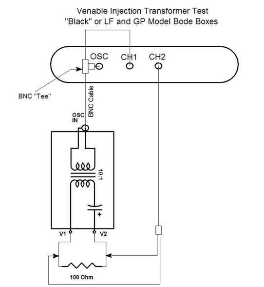
Figure 1 LF and GP Bode boxes (black)
Items Needed
- 2 BNC-BNC cables
- 1 BNC-Minigrabber Cable
- 1 BNC-T Connector
- 2 Banana-Minigrabbers (LF Bode Box) or 1 BNC-Minigrabber Cable (GP Bode Box)
- 1 100-ohm Metal Film Resistor (thru-hole)
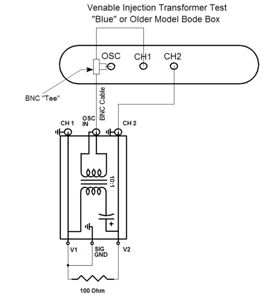
Figure 2 200-000 to -004 Bode boxes (blue)
Items Needed
- 3 BNC-BNC cables
- 1 BNC -T
- 3 Banana-Minigrabbers
- 1 100-ohm Metal Film Resistor (thru-hole)
Procedure
- Connect Ch.1 and the Generator output together on the analyzer and to the OSC IN on the Bode Box using the BNC-T and two BNC cables. See Figures 1 or 2.
- If you have a 200 series Bode Box, connect Ch.2 on the analyzer to the CH2 BNC connector on Bode Box using the third BNC cable, as in Figure 2. If you have the newer model LF or GP Bode box, connect Ch.2 across the 100-ohm resistor using a BNC-Minigrabber cable, as shown in Figure 1. Go to step 4 if you are not measuring a GP Bode Box.
- GP bode Box only: Connect the GP Bode Box BNC output across the 100-ohm resistor using the second BNC-Minigrabber cable and skip to step 6.
- All models except the GP Bode Box: Connect V2 on the Bode Box to one lead of the 100-ohm resistor using a Banana-Minigrabber and connect V1 on the Bode Box to the other lead of the 100-ohm resistor using a Banana-Minigrabber. Skip to step 6 if you are measuring a newer LF Bode Box.
- If you have a 200 series Bode Box, connect SIG GND to V1 on the Bode Box using the third Banana-Minigrabber as in Figure 2. See the Note below.
- Conduct a sweep with the analyzer from 2 decades below the lowest frequency range to 2 decades above the highest frequency range printed on the Bode box cover.
Test Results
Gain: In Figure 3, the tester should see a flat -20 dB passband that rolls off at about 1 decade below where there is minimum phase shift to 1 decade above in a conventional injection transformer. An electronic injection transformer will have a flat -26 dB passband that is DC coupled and rolls off at high frequencies, as shown in Figure 4. The frequency pass band will be shifted up or down in frequency depending on the Bode Box model. The frequency range is printed on the Bode Box cover.
Phase: For a conventional injection transformer, the tester should see a 0 deg. or 180 deg. phase shift in the passband depending on the test connection (See Note). There will be a more positive phase shift near the low frequency roll off and a more negative phase near the high frequency roll off, as seen in Figure 3. For an electronic injection transformer, the tester should also see a 0 deg. or 180 deg. phase shift in the passband depending on the test connection with a more negative phase shift approaching the high frequency roll off. Only the 0 deg. Phase shift is shown in Figure 4.
Note:
For the older model blue Bode Boxes, connecting Ch.2 on the analyzer to the Ch.1 connector on the Bode Box and grounding V2 instead of V1 will result in a 180 deg. phase shift on the Bode Box transfer function Bode plot. For the newer model black Bode Boxes, swapping the Ch. 2 connections to V1 and V2 will result in a similar 180 deg. phase shift in the Bode Box transfer function.
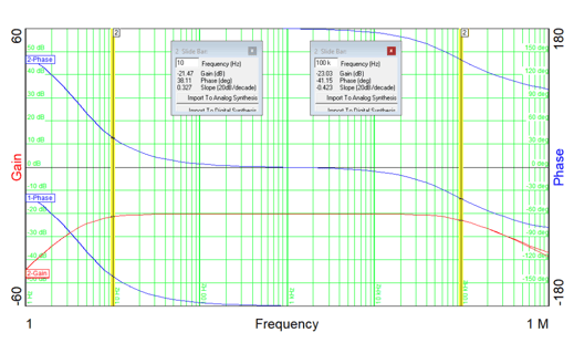
Figure 3 200-002 “Bode Box” Electronic Injection Transformer
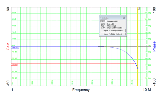
Figure 4 200-004 “Bode Box” Electronic Injection Transformer