“Feedback is so essential that engineers who don’t understand it should be legally barred from circuit design,” said MIT Professor Jim Roberge, stressing the point that a full understanding of feedback is essential to good circuit design.
This blog post provides an introduction to the topic, which is covered in great detail in this Venable Instruments white paper, Optimum Feedback Amplifier Design.
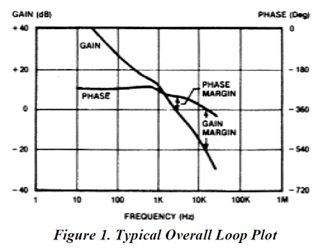
Many circuit designers think of control system feedback loop compensation only in terms of stability; stable or unstable. Normally we define stability using the bounded-input, bounded-output (BIBO) definition that a system is stable if every bounded input produces a bounded output. Stability is usually measured by two factors shown in the Bode diagram (Figure 1) below, phase margin, which is the difference between actual phase lag and 360° when the loop gain is unity (usually expressed in degrees); and gain margin, which is the amount the gain has fallen below unity when the total phase lag is 360° (usually expressed in dB).
It is instability, rather than the insufficiency of available gain, that usually limits the performance of feedback systems and the white paper shows:
-
- There is an optimum error amplifier transfer function for any given loop crossover frequency and phase margin.
- The optimum design is one with the highest gain below crossover and the lowest gain above crossover.
- There is a unique pole-zero placement to achieve optimum performance. This pole-zero placement and resultant circuit component values can be determined without trial-and-error.
- There is an optimum open loop crossover frequency (loop bandwidth) for any given phase margin.
- Optimizing the performance of a feedback control loop can be done with techniques that are simple, effective, and easy to apply on single or multiple loop systems of any type and will yield optimum results without the usual trial-and-error process.
- Three new concepts are introduced: the concept of phase boost as the single variable of importance in loop stability, K-Factor as a convenient method of defining both phase boost and the shape of the Bode gain curve, and the concept of a Figure of Merit for evaluating the relative performance of various loop compensation.
A simple, straightforward method exists for achieving optimum control system performance without trial-and-error. For the full detail please download the Venable Instruments white paper, Optimum Feedback Amplifier Design.