Anyone who has wielded a hand-held multimeter has enjoyed the convenience of placing two isolated leads at any two points on or in a circuit to perform spot checks of continuity or measure Voltage drop or resistance. For quick checks—particularly ones where a power source is distinct from the measurement device—this process is adequate; but, when a Voltage drop must be measured to a greater degree of accuracy—both in terms of meter output and circuit location—this type of probing and sensing is not adequate. Moreover, in any testing application where current or Voltage is controlled the requirement for independent positive and negative Voltage and current sense is obvious. For this reason advanced battery testing instrumentation, such as Venable Instruments’ ESTi platform, provide discrete input-output for each of these parameters; and the following examples illustrate the rudimentary principles and some more advanced applications of these forefront instruments.
Rudiments
Two-point measurement
In the case of Figure 1, note that the Voltage and current sense share the contact and most of the wiring. The obvious intent is to determine the value of R by measuring DV across the resistor and employing Ohm’s law, E=IR, by dividing the potential drop by the known current—constant in a series circuit.
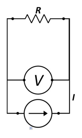 Figure 1 - Simplified 2-point I, V, Measurement Scheme
The problem is that what is measured is not only the potential drop across the passive component, R, but also the wiring that the current source and the Voltage sense share with one another. The real picture looks more like Figure 2, where one can see that the potential difference measured by the meter will include two lengths of wire with finite resistance, r, in addition to the target component. Thus, the Voltage drop measured will be ; and the error will amount to the ratio of .
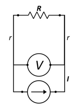 Figure 2: Circuit Showing Additional Resistances Combined in the Potential Measurement
For an active device, such as a battery, the situation persists; resulting in a similar error. However, the sign of the error depends upon the direction of the current. In the circuit analogous to Figure 2, (See Figure 3.) we see R replaced with a battery.
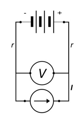 Figure 3: Simplified Battery Circuit with Two-Point V Measurements
Now; when the current is flowing in a positive direction (i. e., toward the positive terminal), the error of 2r will be added to the terminal Voltage of the battery, resulting in an artificially high potential reading and leading to an error that has been discussed in an earlier posting. When current is reversed, however, the potential error will be subtracted from the terminal Voltage measurement and could result in premature cut-off of discharge and a falsely low discharge capacity.
Four-point measurement
The remedy for these bipolar errors is four-point or Kelvin measurement, named after William Thomson(Lord Kelvin), who is credited with having devised the 4-terminal sensing method for measuring low resistances. The improved sensing circuit is shown below in Figure 4; note how the Voltage sense leads are placed 1) proximal to the device terminals and 2) inside the current contacts.
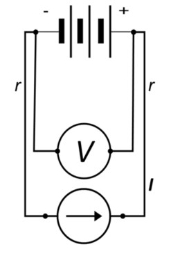 Figure 4: Battery Circuit with 4-Point (Kelvin) Sensing
In this manner the Voltage drop attributable to the length of current-carrying wire, 2Ir, is virtually eliminated.
Implementation
For some common configurations specialized cell holders that provide independent V, I sense have been fabricated. Figure 5 shows a universal cell holder designed by Venable Instruments, showing clearly the 4 contacts.
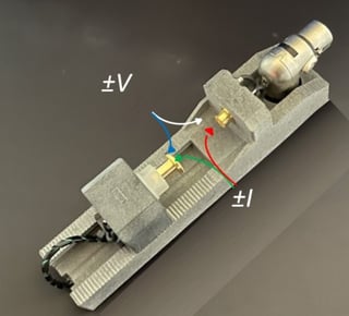 Figure 5: Polycell Holder; Indicating Independent V, I Contacts
These fixtures may be adjusted to accommodate and connect to cylindrical cells; such as 18650, 17450 and 21700; and coin cells; such as 2032, 1620 and 2016. (See Figure 6.) In each configuration potential measurement is ensured without inducing any Ohmic effect between the sensor and the point of contact.
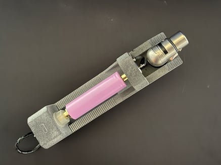
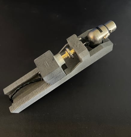
Figure 6: Polycell Holder with 18650 and 2032 Cells in Place
For more general testing of electrochemical devices or systems, Venable Instruments effects Kelvin measurement by fabricating and supplying test leads that contain four leads—±V and ±I, Figure 7, shown connected to a commercial energy storage device.
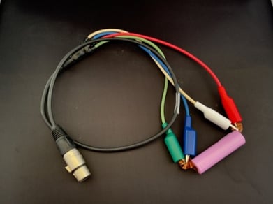 Figure 7: Customer Test Leads Connected to Tabbed Cell
Again, note that the Voltage sense leads are placed inside the current sense leads. In some cases the contact points on the device may provide insufficient surface area for both pairs of leads. In those instances the Voltage sense should be placed directly on the device, and the current sense should be clipped to them.
Applications
Having the flexibility of the customer test leads enables users to perform fundamental experiments on electrochemical systems that may pertain to materials testing or characterization of electrochemical couples for energy storage devices. In these types of experiments, the current leads—referred to as working and counter electrodes—circumscribe the cell(circuit) and the Voltage leads—referred to as reference electrodes—can isolate one half-cell.
Electrochemical
Potentiometric
Electrochemical experiments are conventionally performed with three electrodes—working, counter and reference—with current being supplied in order to maintain a controlled potential between the working and reference electrodes. (See Figure 8.) These Voltammetric experiments are critically dependent upon the accuracy and precision of the potential measurement, and the independence of the reference sense from the current prevents the errors that have been discussed above from affecting experimental results.
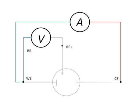 Figure 8: Kelvin-type Connection in Three-Electrode Electrochemical Cell
The basis of Voltammetric experiments is the control of the potential between the working electrode (WE) and reference electrode (RE). The low sense is attached to RE so that WE is always reported as positive or negative with respect to the reference—often a saturated calomel or Ag|AgCl electrode; and the negative current (sometimes called “low force”) is connected to CE so that the current sign follows convention of anodic (+) or cathodic (-), depending upon whether the WE is experiencing oxidation or reduction. This set-up is ideal for corrosion studies, kinetic experiments, physical chemical studies of boundary orbital separation, chemical analysis and characterization of energy storage devices or materials.
Spectroscopic
Moreover, the capability for distinguishing potential measurement, control from current application is the gateway to a plethora of more sophisticated techniques under the broader heading of electrochemical impedance spectroscopy (EIS). In EIS the same connection scheme that has been illustrated in Figure 8 may be employed for conducting an array of experiments that can provide passive (dc resistance) and active metrics (impedance, capacitive reactance) of the device or material and equivalent circuit-fitting parameters. When discrete devices, such as cells or fuel cells, are tested; the electrode isolation provided by the PolyCell (See Figure 5.) permits determination of the resistive, capacitive and inductive behavior of the cell. This scheme is blocked in Figure 9; where a ripple current is applied over a potential control, measured by frequency response analyzer and parsed into passive and active components of the signal.
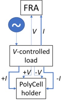
Figure 9: Block Schematic of EIS Connection through PolyCell Holder
The details of how EIS is performed is discussed in another white paper here, but the fundamental output of an EI spectrum analysis are two plots that describe the current and frequency (“phase shift”) response—the Nyquist plot and the Bode plot.
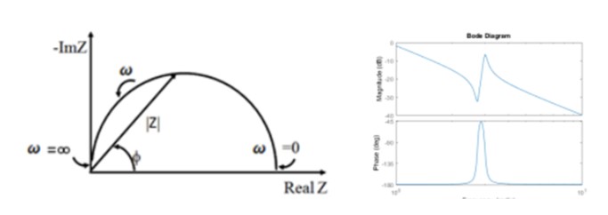
Figure 10: Nyquist (left) and Bode (right) Plots that Result from Applications of EIS Analysis
The former graph shows the real component of the complex impedance on the abscissa and the imaginary component on the ordinate. As the white paper offers, the shortfall of the Nyquist plot is that the frequency, w, is not immediately shown. The Bode plot, however, provides this complementary parametric information. These data may then be fit with high-order polynomials whose variables correspond to different circuit components; such as capacitors, resistors and inductors; that may model the behavior of the system or device.
Device Studies
When a solid-state, integrated device; such as a cell or battery; is the system under study: the connection above reverts to Figure 4, where only the terminal potential is known. With such a circuit the internal resistance of the device may be determined readily via pulsed dc or ac methods.
Example:
Academic researchers investigated the internal resistance (IR) of lithium-based cells of varying capacities and determined the IR of a 100-Ah cell to be ca. 2mΩ.[i] The test current for this cell was 200A. If cabling without the additional Voltage sense were employed, the resulting Voltage measured at the source would reflect not only the intrinsic value of the cell but also the Voltage drop along the cable. Assuming that 4AWG cable was used and two lengths of 10’ were connected from the source to each of the terminals (reasonable to assume but not stated in the reference), one calculates the additional Ohmic resistance to be almost 5mΩ[ii]—significantly more than the cell’s value.
Again, this type of test characterizes the performance of a sealed production article. If, however, a reference electrode or an intermediate contact to the plate or electrode separator can be inserted (gray barrier between +, - electrodes); then a three-electrode circuit may be arranged, as in Figure 10. In this way the potential increase [or decrease, depending upon polarity] of anode or cathode may be monitored during charge or discharge.
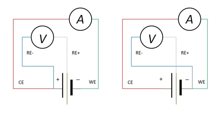
Figure 11: Devices Studies with Kelvin Connections; (a) Cathode-Specific, (b) Anode-Specific
Example:
However, the potentials of these reactions change over time, such that the overall cell potential decreases and with it functional discharge capacity. Using the connection in Figure 10 b), the behavior of the cathode with respect to a Li+|Li reference electrode has been observed; (See Figure 11.) note that the potential increases (right ordinate), resulting in a reduction in the terminal Voltage of a cell and a hastening of the approach to the cut-off Voltage (right ordinate) during discharge.
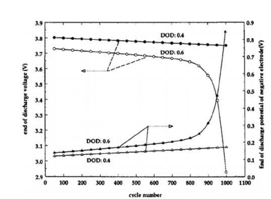 Figure 12: End-of-Discharge Negative Electrode Potential vs. Cycle Index iv
Without the flexibility of the Kelvin connection, such a study of either electrode or the supporting electrolyte would not be possible.
Summary
As we have expressed above, Voltage measurement is critical to device characterization; but simple mechanical flaws in measurement circuits and fixtures can result in errors that can contribute to perceived nonconformances in device performance. By imposing simple controls in designing test circuits and fixtures, such as the Venable Instruments Polycell holder; however: these errors can be effectively eliminated and ensure accurate evaluation of critical energy storage devices and circuit components. Furthermore, the range of experiments that may be performed with an ESTi energy storage analyzer is greatly expanded because of the capability afforded by 4-electrode (Kelvin-type) measurement.
[i] D. Anseán et al., “DC internal resistance during charge: analysis and study on LiFePO4 batteries,” proceedings of EVS27; Barcelona, Spain, 11/17-20, 2013
[ii] from www.inchcalculator.com/wire-gauge-size-and-resistance-calculator, accessed 12/30/2020
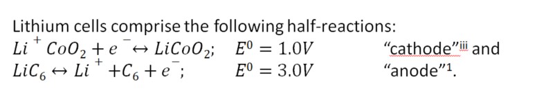
[IIi] The terms "anode" and "cathod" typically refer to the electrod polarities durning the discharge cycel; the more general terminology is "positive" and "negative" electrodes.
[iv]from “Cycle Life Modeling of Lithium-Ion Batteries,” Journal of the American Chemical Society, 151(10), 2004