Frequency Response Analyzers are often used to measure power system feedback loop response, impedance vs frequency of source -load impedances, and of passive components. They can also be used to measure the characteristics of semiconductor devices such as the open loop gain of an operational amplifier.
The open loop gain of an operational amplifier or op amp is the output voltage divided by the difference between the noninverting and inverting inputs of the amplifier as shown in equation 1. The typical gain of an op amp ranges from 104 to 105 or higher. Because the gain is so high, the input signal for an op amp must be very small to keep the op amp's output within its linear range In fact, it is nearly impossible to measure this gain with the loop completely open.

However, there is a technique that can be used to measure the loop gain or open loop gain of an op amp. The open loop gain or the gain around the feedback loop can be measured with the loop closed by injecting a signal in series with the feedback loop at the correct point in the feedback loop. There are two criteria used to select the correct point to inject into the feedback loop path. The first one is to find a point where the loop is confined to a single path and the second, is to find a point where a low impedance is driving into a high impedance. The only place where the feedback loop meets these criteria is the point where the loop senses the output voltage as shown in Figure 1.
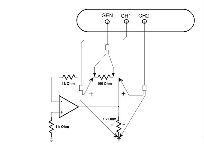
Figure 1. Op Amp Open Loop Gain Measurement
A 100 ohm injection resistor is inserted in series with the loop at that point. For this example, the input to the amplifier is grounded or biased to a fixed set point for the open loop gain measurement with a 1k resistor and a 1k resistor is used as a load. Additionally, for an op amp loop gain measurement another resistor is inserted between the injection point and the inverting input to maintain the condition of a low impedance driving into a high impedance. Even though the input impedance of the inverting input is high it acts as a virtual ground. A 1k resistor was chosen for Figure 1 but lower value resistor could be used as long as it maintains an impedance ratio of low output to high input impedance of at least 100 to 1 to get a reasonably accurate measurement as seen in equation 2.

Referring to Figure 1, the floating generator of the analyzer is connected across the injection resistor. In the case of an analyzer without a floating generator, the floating secondary of the injection transformer is connected across the injection resistor. Channel 2 is connected to the output or low impedance side and Channel 1 is connected to the input or high impedance side of the injection resistor. A frequency sweep is done from a lower frequency until just past the loop crossover at higher frequency.
In many cases, the op amp open loop gain is going to be so high that no analyzer will have the resolution to measure it at low frequencies even if you inject as much signal as you can into the circuit. However, the loop crossover and phase margin can still be verified. As a side note, on Venable plots the phase margin is measured from the 0 or 360 degree phase line because the analyzer measures the inversion of negative feedback loop.