Tuttle’s Topics
This is the fourth installment of a multi-part series of blogs that discusses feedback loop control
design concepts, analytical methods and tradeoffs. Although we will use power supply
examples, the concepts (as Dean Venable oft reminds us) apply to all servo loops. We will do
this with a minimum of math, and focus on developing an intuitive understanding of system
behavior. In this installment, we examine the compensation (feedback) concepts used to close
the loop and achieve desired design behavior (crossover frequency and phase margin in the
frequency domain, transient response in the time domain).
“Closing the Loop- Feedback Circuits”
In previous installments, we have discussed graphical analytical methods, and how and why the system responds the way it does. In this installment, we will open the “black box” of compensation that was referred to in the last blog regarding closed loop performance and see how we can achieve the desired closed loop performance.
So far, we have discussed the crossover frequency and phase margin for a closed loop feedback system (for more on phase margin, please read “How Much Phase Margin Do I Need?”). Additionally, we have discussed how the poles and zeros of the closed loop transfer function manifest themselves in both the frequency domain (Bode plots of gain and phase) and time domain (transient response). Given that the poles and zeroes of the modulator (plant) are intrinsic, we are left with the poles and zeroes of the compensation (feedback) circuit to manipulate for a desired closed loop behavior (for more on power supply modulators transfer functions, read “Stability Analysis of Feedback Loops Part Two”).
So how do we manipulate the poles and zeroes in the feedback circuit? The approach that most engineers use is to implement an error amplifier with the appropriate passive components to control the overall compensation circuit’s gain and phase. There are three common error amplifier circuit topologies used to do this. We shall call them Type 1, Type 2 and Type 3 and examine their features.
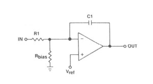
The Type 1 error amp configuration is also known as an integrator and is shown below:
Figure 1. Type 1 Amplifier Schematic
The Type 2 error amp configuration has an additional pole-zero combination and is shown
below:

Figure 2. Type 2 Amplifier Schematic
The Type 3 error amp configuration has two pole-zero pairs and is shown below:
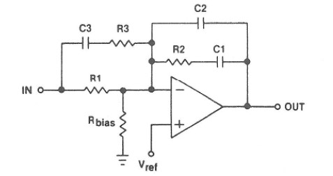
Figure 3. Type 3 Amplifier Schematic
So, which error amplifier configuration should one use? That depends entirely on the plant (modulator) transfer function and the crossover frequency, phase margin and gain margin desired for the closed loop. Dean Venable introduced a method to simplify the stability analysis of feedback systems, called the K-Factor. The K factor analysis method allows engineers to start from the desired crossover frequency and phase margin, and work backwards into the compensation circuit design. The K-Factor analysis is detailed in Dean Venable’s paper “The K Factor: A New Mathematical Tool for Stability Analysis and Synthesis”. Dean Venable’s paper builds on Wayne Tuttle’s paper, "Relating Converter Transient Response Characteristics to Feedback Loop Control Design."
Venable Instrument’s Stability Analysis Software features circuit synthesis based on the K-Factor analysis, and supports simulation of the synthesized circuit. With the Stability Analysis Software, one can specify the closed loop crossover frequency and phase margin and synthesize the error amp/feedback circuit. Once simulation of the synthesized feedback circuit is completed, the user can combine the results mathematically with the measured modulator
behavior (measured with a Venable Frequency Response Analyzer) and observe that the closed loop performance meets the desired outcome. Once the closed loop system is built, one can then measure the closed loop performance with the FRA to show that, indeed, the closed loop performance meets specification.
We have examined three feedback circuits that are most commonly used for compensation. Although they are “power supply centric”, the analysis methods will work for any servo loop. Venable Instruments provides the hardware and software tools that make closed loop stability analysis a science, as opposed to an art (or a “black art” as some think).