In this blog post, we will look at the three basic topologies from which all switching power converters can be derived and their input to output transfer functions. We will also examine the power stage characteristics of the voltage mode buck converter operating in continuous conduction mode (CCM). We will then define control to output transfer function equation and the location of its poles and zeros. Access Part 1 of the Series.
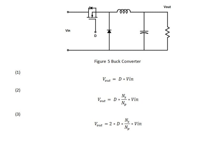
There are basically three different topologies of switching power supply plants or modulators: the buck converter, the boost converter and the buck-boost converter. The buck converter, in Figure 5, steps down the voltage while stepping up the current. Forward, half bridge, push-pull, and full bridge are all buck converter derived topologies. The voltage input to output transfer function is shown in Equation 1, where variable D is the switch on time duty cycle. An Isolated buck derived transfer function will also include the transformer turns ratio as shown in Equation 2 and in the case of the push-pull, and full bridge converters, twice the transformer turns ratio. See Equation 3.
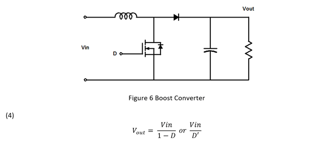
 The boost converter, in Figure 6, steps up the voltage while stepping down the current. The boost topology is often used in battery applications, LED drivers, and power factor correction circuits in off line power supplies. The voltage input to output transfer function is shown in Equation 4 where D’ or 1-D is the switch off time duty cycle.
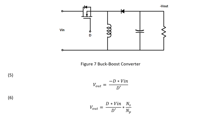
The buck boost converter, in Figure 7, can both step up and step down the output voltage and in its most basic form also inverts the output voltage. The fly back, single-ended primary inductor converter (SEPIC) and the output inverting Cuk converter are buck- boost derived topologies. The voltage input to output transfer function, shown in Equation 5, is the ratio of the switch on time over the switch off time. Isolated buck boost derived transfer functions, like the fly back, also include the coupled inductor turns ratio like Equation 6.
The control to output transfer function, also called the plant or modulator has to be measured first in order to design a compensator. Then, the error amplifier can be designed to set the bandwidth or crossover frequency and the phase margin for the feedback loop.
In continuous conduction mode (CCM), the control to output transfer function of a voltage mode or voltage feedback buck converter has a flat gain with very little phase shift at low frequencies. This is the gain of the modulator. The modulator consists of a comparator with a fixed frequency linear ramp or saw tooth waveform fed into the negative input and the control voltage output of the error amplifier connected to the positive input. The output of the comparator is pulse width modulated (PWM) signal that is proportional to the control voltage. The PWM is applied to the transistor and switches it on and off. The low frequency gain is simply the input voltage of the converter divided by the ramp voltage in Equation 7.
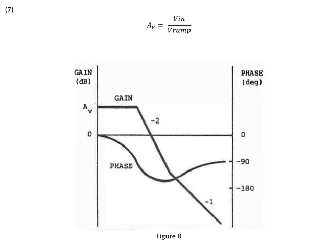
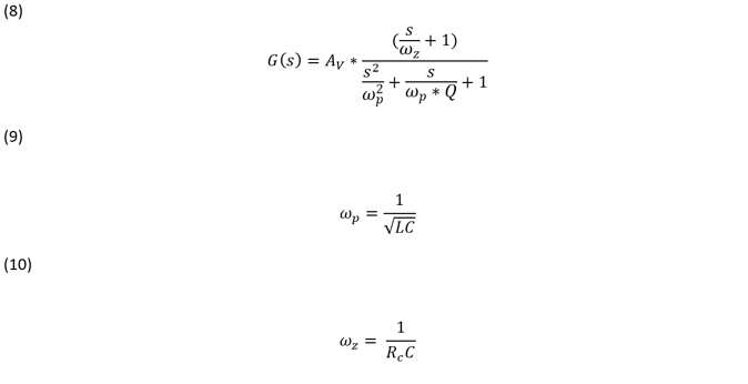
Figure 8 is a typical transfer function for a voltage mode buck converter power stage. The output L-C filter averages the PWM signal to DC. It also adds a complex conjugate or double pole to the plant transfer function as shown in Equation 8. At the frequency of the double pole, see Equation 9, the transfer function begins to roll off at -40 dB/decade and this slope is associated with -180 degree phase shift. Equation 10 gives the location of the left half plane zero at higher frequencies caused by the interaction of the filter output capacitor and its equivalent series resistance (ESR). This zero reduces the transfer function roll off to -20 dB/decade and the phase shift to -90 degrees of phase.
The quality factor or Q of the L-C filter will affect the transfer function of the plant. As the Q gets larger, there is less damping in the filter and the filter transfer function peaks up at the resonant frequency. The phase shift begins closer to the resonant point, the slope of the phase is a lot steeper and it approaches -180 degrees of phase shift faster as frequency increases. A high Q could cause instability or ringing and reduce the bandwidth at which the loop crossover can be set because of the excessive phase shift.

These are, of course, simplified equations and don’t include the series resistance of the inductor, capacitor, diode, or the transistor switch. The losses from these resistances won’t affect location of the left hand plane zero but they will affect the Q by reducing it and the location of the corner frequency of the output filter. The equations for the voltage mode buck derived topologies also show that frequency response of the power stage is not affected by the operating point. This is not true for other topologies. In general, this is why only buck derived converters use voltage mode control.
To summarize, there are three basic switching power supply topologies from which all topologies can be derived. This includes their input to output transfer functions, as well as their control to output transfer functions. Buck derived converters control to output transfer functions are largely not affected by changes in the operating point. The next post, Stability Analysis of Feedback Loops-Part 3, will look at the boost, buck boost switching power supply topologies and their control to output transfer functions and how current mode control affects the control to output transfer function of the three basic topologies.
Related Content
Stability Analysis of Feedback Loops Part Three
Stability Analysis of Feedback Loops Part Four
Best of Content Loop Stability Analysis