Why do stability analysis? There are many reasons. First, to assure that the feedback loop is free from oscillations under all conditions of line, load, and environment. Minimize the circuit response time to transient disturbances. Minimize input filter requirements by maximizing loop bandwidth. And finally, minimize the power supply’s output impedance and improve transient load response.
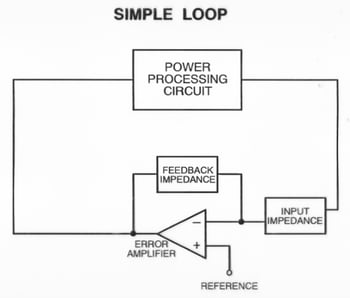
Figure 1 A Simple Feedback Loop
The first thing to consider is the basic feature's of feedback loop as shown in Figure 1. It consists of a power processing block called the modulator or plant and an error detecting block called the error amplifier or compensator. An output variable, such as voltage, is sensed and compared to a reference. The difference between the two is inverted then amplified and used to control the modulator. This works well at DC but higher frequencies reactive components and time delays will cause phase shifts around the feedback loop. Once the phase shift reaches 360 degrees and if the gain is 1 or greater oscillation will occur because the feedback has now become positive.
Avoiding instability is why it is necessary to measure the open loop or loop gain. It is the gain around the feedback loop. In Figure 2, the loop gain is actually –GH where G is the plant or power stage transfer function and H is the error amplifier or compensator transfer function. The negative sign is the inversion of the output of the loop typically caused by the inverting error amplifier. Any frequency response analyzer will measure this inversion or extra 180 degrees of phase shift when measuring loop gain. This is why gain and phase margin are measured in reference to 0 or 360 degrees on Venable gain-phase plots. For more information see the blog post on Determining Gain and Phase Margins on Venable Bode Plots.
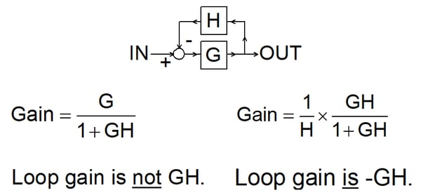
Figure 2 Loop Gain
The transfer function measurement of the overall loop gain or Bode Plot is measured by injecting a signal into the loop and plotting the magnitude in decibels and phase in degrees of the output of the loop divided by the input versus frequency. The gain margin and phase margin of the open loop gain is determined from this plot as shown in Figure 3. The gain margin in dB is the amount of open loop gain at 360 or 0 degrees phase shift to make the closed loop system unstable. It is the difference in gain between 0 dB and the measured gain where the phase crosses 360 or 0 degrees. The phase margin is the amount of extra open loop gain phase shift at the unity gain crossover needed to make the closed loop system unstable. It is the difference in phase between 360 or 0 degrees phase shift and the measured phase at the unity gain crossover.
.
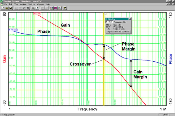
Figure 3 Venable Loop Gain Plot of Gain and Phase Margin
To compensate the feedback loop the modulator or control to output transfer function has to be measured. The modulator consists of the pulse width modulator, the switches, consisting of a transistor and a diode or another transistor, and an LC filter, consisting of inductor and capacitor. The control to output transfer function is measured using the same injection point as measuring a feedback loop except one measurement channel, V3, is connected to the output of the error amplifier while the other channel, V2 is connected at the output of the power supply as shown in Figure 4.
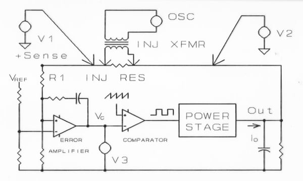
Figure 4 Loop Gain Measurement Injection Point
It is possible to measure the control to output transfer function with loop open and the power supply biased up to the operating point using Frequency Response Analyzer generator DC offset feature as long as the open loop gain is not too high. In most cases, this is not possible and it is much easier to make this measurement with the loop closed.
To summarize, it is a necessity to measure the feedback loop of switching power supplies to ensure loop stability under all line and load conditions. The control to output transfer function of the feedback loop, also called the plant or modulator has to be measured first when designing the feedback loop. Then, the error amplifier compensation can be designed to set the bandwidth or crossover frequency and the phase margin for the feedback loop. The next post, Stability Analysis of Feedback Loops-Part 2, will look at the three basic switching power supply topologies and their transfer functions.
Read Related Content:
VENABLE STABILITY ANALYSIS SOFTWARE
FRA STABILITY ANALYSIS VERSION 6
BEST OF CONTENT - LOOP STABILITY ANALYSIS