In this blog post, we will look at the power stage characteristics of the voltage mode boost and buck-boost converters operating in continuous conduction mode (CCM) as we did for the buck converter in Stability Analysis of Feedback Loops Part Two and Stability Analysis of Switch Power Supply Feedback Loops. We will define control to output transfer function equations and the location of the poles and zeros for these two topologies.
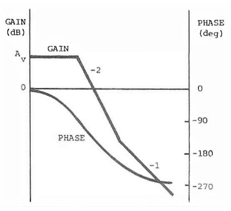
Figure 1.
Figure 1 is a modulator transfer function for a CCM voltage mode boost or buck-boost converter. They both look very similar to the buck converter modulator transfer function. The control to output transfer function of a voltage mode buck-boost or a boost converter, like the buck converter, has a flat modulator gain with very little phase shift at low frequencies. Similarly, there is also complex conjugate or double pole in the plant transfer function which rolls off at -40 dB/decade with a -180 degree phase shift.
There are major differences, however. The transfer functions of the boost and buck-boost converter have gains, poles, and zeros, with the exception of the ESR zero, that are dependent on the operating point. Both topologies have an additional right-half plane zero in the control to output transfer function (plant). The zero causes a reduction in the slope from -2 to -1 like a left hand zero does but the phase is shifted a further 90 degrees negative instead of positive 90 degrees.
The low frequency gains of the boost and buck-boost are the input voltage divided by the ramp but are also dependent on the operating point and the inverse of the square of the off time duty cycle as seen in equation 1. The low frequency gain is inversely proportional to the input voltage and the gain will increase as the input voltage decreases and vice versa.

Both converter topologies have a transfer function of the same form, as shown in equation 2, with a complex conjugate double pole and a left hand plane zero, and a right half plane zero. Unlike the buck topology, power is delivered to the output when the switch is off. The output will actually drop at first if it is trying to increase before increasing. This control reversal is characteristic of a non-minimum phase system with a right half plane zero. The left half plane zero, just like the buck topology, is caused by the interaction of the filter output capacitor and its equivalent series resistance (ESR), as in equation 3.


The frequency of the double pole where the transfer function begins to roll off at-40 dB/decade is also operating point dependent for both the boost and buck-boost converter. The double pole corner frequency is calculated by dividing the inductor value with the square of the off time duty cycle and plugging the effective inductor value into the equation for the corner frequency, see equations 4 and 5 below. The corner frequency is proportional to the input voltage and the corner frequency will decrease as the input voltage decreases and vice versa.

The right half plane zero is dependent on the ratio of the load resistance to the inductor times the square of the off time duty cycle for the boost inductor in equation 6. The right half plane zero buck-boost converter has a similar equation but the inductance is multiplied by the duty cycle on time, see equation 7. A heavier load will move the right half plane pole to a lower frequency and the phase shift will be greater. A lighter load will have the opposite effect.

The Q of the L-C filter for both the boost and buck-boost converter is also operating point dependent on the off time duty cycle as seen in equation 8. The Q or quality factor is proportional to the input voltage and inversely proportional to the load. So, a boost or buck-boost converter with a higher input voltage or a lighter load will have a higher Q. There will be a higher peak and a larger phase shift at the corner frequency of the double poles.

These are simplified equations and don’t include the series resistance of the inductor, capacitor, diode, or the transistor switch. The equations for the voltage mode boost and buck-boost derived topologies show that frequency response of the power stages are definitely affected by the operating point. Changes in the input voltage will have the greatest effect by changing the lower frequency power stage gain and the location of the corner frequency of the LC filter. Increasing the load will cause the right half plane zero to move to lower frequencies. The loop crossover point is greatly restricted since it should be about 20% of the right half plane zero frequency because of excessive phase shift. This is why boost and buck-boost derived converters typically use current-mode control. Even though the right half plane zero is still present, the reduction of the filter double pole to a single pole with current mode control reduces the excessive phase shift and makes these topologies much easier to compensate.
To summarize, boost and buck-boost derived converters control to output transfer functions are greatly affected by changes in the operating point caused by changes in the input voltage or load. The next post, Stability Analysis of Feedback Loops Part Four, will look at compensating voltage mode power supply control to output transfer functions using the type 3 amplifier.