In this blog, we will examine a critical aspect of successful loop gain measurements, the error signal injection point. We will visit the origins of loop gain measurements and develop a better understanding the importance of injection point selection.
“The Magic Triangle”
When using a Venable Frequency Response Analyzer (FRA), a critical decision must be made and that is the location of the error injection point. The error injection point is the location in the servo loop’s feedback circuit where a small AC voltage is injected by applying an AC current through an “injection resistor”. There are two rules of thumb that must be followed for successful measurement of loop gain (the closed loop transfer function of the servo loop). The rules of thumb are:
- The loop is confined to a single path
- A place where the signal comes from a low-impedance point and drives a high-impedance point.
If we want to better understand where the rules of thumb come from, we must refer to the work done by Dr. R.D. Middlebrook in his paper “Measurement of Loop Gain in Feedback Systems”. In this paper Dr. Middlebrook examines both voltage and current injection methods and presents the strength and weakness of each method. The loop gain voltage/current relationships are shown below:
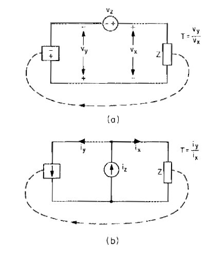
Figure 1. Measurement of T by injection into the closed loop, (a) by voltage ratio, (b) by current ratio
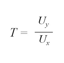
Regardless of method, the measurement of loop gain depends on the relationship of uy and ux, where uy is the modulator output, ux is the feedback input (u can be current or voltage), and the loop gain is defined as:
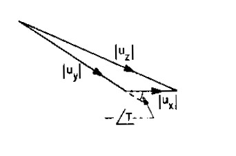
Since both uy and ux are phasors, they can also be represented as:
The models shown here necessarily confine the loop to one path so that the definition of loop gain holds true (Rule 1.)
At Venable Instruments, our Frequency Response Analyzers are used with the voltage injection method. The voltage injection method requires vy (Figure 1.(a)) to approximate an ideal voltage source, which means that the impedance “looking backward” must be very low compared to the impedance “looking forward” for the model to be valid (Rule 2). Generally, the ratio of impedance looking forward to backward should be about 100:1.
We have greatly simplified (possibly over simplified) Dr. Middlebrook’s work in this blog. However, it behooves the reader to know the injection point rules for successful loop gain measurements using a Venable FRA. It is recommended that the reader visit the Venable Vault where additional content from Dr. Middlebrook’s is available.
*Not to worry, one can measure the loop gain of systems with multiple paths.