One technique of design oriented analysis is to break the problem into smaller pieces for analysis. The extra element theorems (EET) including its extension the 2nd extra element (2-EET) theorem are methods that can be used to simplify analysis of any transfer function. The designer can remove one or two impedance components or dependent sources to simplify a circuit and do the analysis and then add the components back successively into the circuit using the EET. The resulting equations will be in low entropy form.
As an example, the input or driving point impedance transfer function of a bridge circuit with five impedance elements can be easily analyzed by inspection after removing one of the elements and then adding it back in with the EET to quickly get the answer. Removing RL, the shunt impedance in Figure 1, results in a circuit with an impedance that can be determined by inspection. See Figure 2.
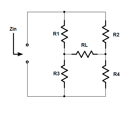 Figure 1
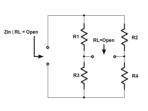
Figure 2
The input impedance with RL removed is:
Two other impedances must be calculated from the open terminals of the resistor RL: Zd and Zn. The input impedance or driving point impedance transfer function of the bridge is determined by using a current source as an input excitation and the output is a voltage response as seen in equation 2.

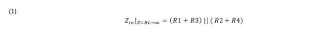
The Zd impedance is determined by setting the bridge input excitation to zero. This is accomplished by setting the terminals of the bridge circuit to open or Iin=0 . See Fig.3. Again, equation 3 impedance is determined by inspection:
Figure 3

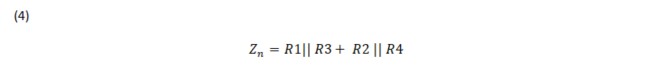
The Zn impedance is determined by using null double injection to null the output of the transfer function. In the case of a self-impedance, shorting the input so that it-nulls the output with Vin=0. See Fig.4. Finally, the Zn impedance is by inspection is shown in equation 4.
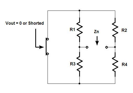
Figure 4
The results of the three calculations above are substituted into the impedance formula for the EET in equation 5. This is the open circuit equation for an extra element or shunt across a node pair. It shows that the transfer function of a linear system is a bilinear function of any single impedance (e.g. Z). The gain is one of any of six transfer functions such as voltage gain, current gain, transimpedance, transadmittance, driving point admittance, and finally the driving point impedance of this example.

The final result for the input impedance is shown in equation 6. Here, Z or RL, the extra element is not used in any of the calculations for input impedance and is only substituted into the EET formula.

The impedance formula for the EET also has a dual where the impedance Z is replaced with a short. Equation 7 is the short circuit equation for adding an extra element in series with a branch. The impedances Zd and Zn are calculated in the same manner from the terminals of the extra element, Z.
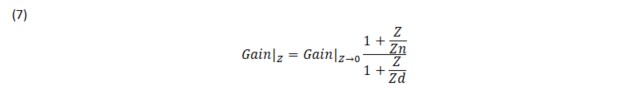
The gain of the open circuit equation and the gain of the short circuit equation are related by the ratio of the impedances calculated from the terminals of the extra element, Z in equation 8.

Video Presentation of Technical Therapy for Analog Circuit Designers Part 2 . A video lecture and notes are under Chapter 6 - Null Double Injection (NDI) and the Extra Element Theorem (EET).
Discussion of the 2-EET theorem is located in the IEEE paper:
Discussion of the 2-EET theorem is also located in: