In this final blog of the series, Measuring the Input and Output Impedance of Power Supplies, I'll cover setting up the injection using the transformer and power amplifier and how to make sure the drive levels are correct and that nothing is being under driven or over driven.
In Part 1 of this series of this series, I covered why source-load impedance measurements are necessary, basic equipment needed, and the setup to make voltage injection impedance measurements.
In Part 2 of this series, covered setting up the current probe properly, determining the correct range and calculating the scale factor with the correct polarity and entering it into the Venable Stability Analysis software.
The Input/Output Impedance Test Set consists of a high saturation current secondary injection transformer and a dc coupled 4-quadrant power amplifier. The primary purpose of the test set is to provide enough drive for the FRA generator to inject a disturbance into the power line and measure the input or output impedance of the “unit under test”.
The injection transformer is capable of handling large amounts of DC current while still coupling an AC signal into the circuit. The injection transformer secondary is rated to 50 or 100 amps DC depending on the model. The 3 dB bandwidth is 30 to 250 kHz, however, the injection bandwidth can be extended from 5 Hz to 500 kHz. The lower bandwidth can be achieved by reducing the AC injection signal level to avoid saturation. The upper bandwidth is a hard limit as the transformer quits working as a transformer due to losses. For current levels higher than the individual transformer ratings, the secondaries of two or more injection transformers, of the same current rating, can be connected in parallel to increase the rated current through the secondary. The primary side can be connected in parallel or in series as shown in Figure 1b.
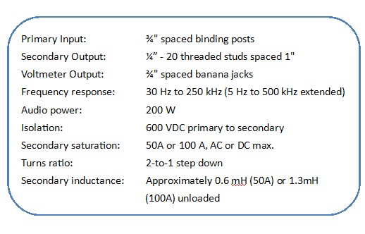
Table 1: Injection Transformer Specifications (see Figure 1a)
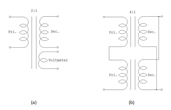
Figure 1: (a) Injection transformer schematic. (b) Injection transformer secondaries connected in parallel
The VLA 1500 amplifier is a 4-quadrant power amplifier rated at 430 Watts rms. Higher power ratings are available on special request. Gain is variable from 0 to 20 V/V and is set with the front panel gain control knob. The small signal bandwidth is DC to 250 kHz, however, the injection bandwidth can easily be extended up to 500 kHz. The primary bandwidth limiting factor in the IOZ test set is the injection transformer. The amplifier, in voltage mode, can operate in three configurations: high voltage, automatic, and high current. The high current configuration is the factory default in order to provide drive into small impedances typically seen in this measurement application. The high current configuration settings can be verified by consulting the Advanced Configuration section of the amplifier manual. Controls for the amplifier are located on the front panel and consist of the on/off switch, gain control knob, push buttons, status and fault indicators as seen in Figure 2 below. Selectable inputs and the output for the amplifier are located on the back panel, as shown in Figure 3. To power up the amplifier, remove or turn down the signal source on the input and set the gain control knob of the amplifier to zero. Depress the power switch on the front panel to turn the amplifier on and wait for the yellow READY and green RUN LED’s to illuminate. The amplifier is ready to be used.
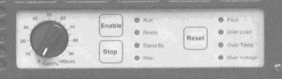
Figure 2: Front Panel Amplifier Controls
The test set up for injecting a disturbance into a power system is straight forward. First, the frequency response analyzer (FRA) generator output is connected to the input of the amplifier and then the amplifier output is connected to the primary of the injection transformer. Finally, the secondary of the injection transformer is connected in series between the power source and load usually after the generator injection level and amplifier gain have been set.
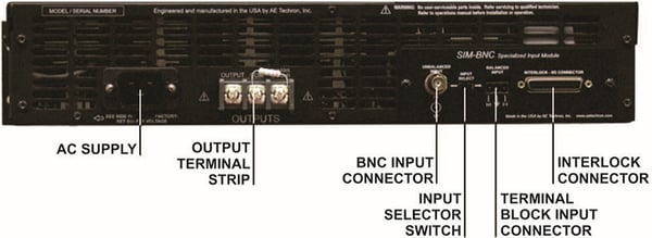
Figure 3: Amplifier Back Panel
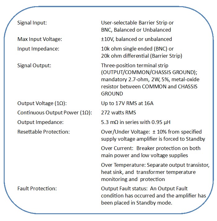
Table 2: VLA-1500 Power Amplifier Specifications
Now let’s go to the subject of injection drive levels. There are three variables in setting the drive level. First, is the level of the Oscillator Output of the FRA; next is the gain setting of the power amplifier, and finally, the 2:1 voltage step down of transformer. Since the output is the product of the transformer 2:1 step down, the generator level and the amplifier gain setting, there are an infinite number of gain setting possibilities for any given output level. The simplest way to set the level is to use one of the gain variables to set the injection transformer output level to the desired level at an intermediate frequency such as 1 kHz and then leave the gain settings alone during the sweep. Another way to set the amplifier gain adjustment is to set the FRA Oscillator Output to a reasonable level like 1 volt peak and then use a voltmeter or oscilloscope to monitor the output of the injection transformer and adjust the gain knob on the power amplifier for a 1 volt peak output value. In this case, the injection level is set directly with the Analyzer Control menu setting in the Venable software. All of this can be done before power is applied; in fact, it can be done before the injection transformer is even connected into the circuit.
For example, let’s say you are testing the impedance of some piece of the International Space Station. The Space Station power bus is 120 VDC and program officials have decided that a 2% variation in the power bus will not damage the equipment. That means that the 120 VDC bus can vary by ±2.4 volts and still be in the safe region. Set the analyzer AC Volts Out to 1 volt peak and then monitor the output of the injection transformer. Adjust the gain control of the power amplifier for ±2 volts peak voltage at 1 kHz. This will give a small margin of safety (from 2 volts to 2.4 volts). The amplitude of the FRA generator output is very flat with frequency. The gain of the power amplifier is also flat with frequency except where the output falls off above 250 kHz. This means that by setting the amplitude in mid-range (1 kHz), the output amplitude will not exceed this value at any time during the sweep.
There are some pitfalls to avoid when injecting into the power line during a source load- impedance test. Driving the injection transformer with a large signal AC at or below the lower bandwidth limit of 30 Hz can cause the transformer to saturate. The transformer primary in Figure 4 below is starting to saturate with a 10 Vpk injection level at 30 Hz. The largest allowable injection level will drop with frequency and may be quite low at lower frequencies. It’s a good idea to monitor the injection signal with an oscilloscope especially when making measurements below 30 Hz.
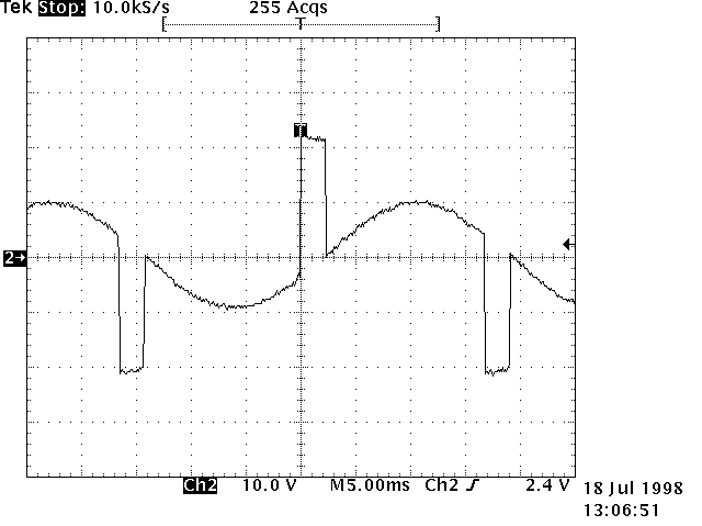 Figure 4: Over-driving the Transformer Primary at Low Frequencies
Impedance measurements are small signal measurements. It is good practice to minimize the injection level as much as possible and still get a smooth, noise free data plot. There are three ways to reduce noise, one is to increase the output of the FRA, another is to increase the integration time or cycles, and the final way is to increase both. An increase in the injection level will move the smallest channel measurement away from the noise floor. Of course, there is a practical limit to how much signal can be injected. An increase in integration time or cycles increases noise rejection in the measurement but will slow down the sweep. To adjust out the noise, the FRA voltage readings on Ch. 1, Ch. 2, or even Ch. 3 should be monitored. The channel voltage readings in the Venable software are located on the Analyzer Control menu in the grayed text boxes below the Take Data at Start Frequency button. The Take Data at Start Frequency button is used to take measurements at one frequency and allow the user to adjust the AC injection signal level and the integration time until the channel voltage readings are stable. The point where the noise problem will be the worst is where the measured impedance is very high, very low or at frequencies where there is noise such as power line harmonics. See Figures 5, 6, and 7 below.
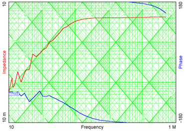
Figure 5: A Noisy Impedance Plot with Short Integration Time
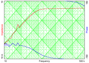
Figure 6: A Noisy Impedance Plot with an Inadequate Injection Level
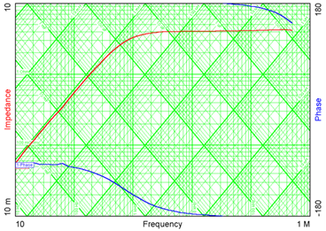 Figure 7: A Good Measurement Plot
To summarize, the Input/Output Impedance (IOZ) Test Set consists of an injection transformer with a high saturation current secondary and a dc coupled 4-quadrant power amplifier. The amplifier and injection transformer provide the drive and isolation necessary to disturb the power line with an AC signal when connected to the analyzer generator. It is a good idea to monitor the AC injection level with an oscilloscope, especially at frequencies below 30 Hz, in order to avoid saturating the injection transformer. Keep in mind that power supply input and output impedance measurements are small signal measurements. Adjust the injection level and integration time or cycles to minimize the injection level, as much as possible, and still get a good smooth noise free plot.
Read prior blog posts:
Measuring Impedance of Power Supplies - Current Probe and Scale Factor (Part 2)
Measuring the Input and Output Impedance of Power Supplies (Part 1)