In Part 1 of this series, I covered why source-load impedance measurements are necessary, basic equipment needed, and the setup to make voltage injection impedance measurements.
Impedance measurements are a lot trickier than they look. The hardest part is getting the current probe set up properly. The other is determining the scale factor with the correct polarity and entering it into the Venable Stability Analysis software. This blog post will take you through those steps.
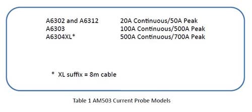
Let’s start with the current probe system. If you want good performance at low frequency, choose a DC current probe system such at the Tektronix AM503. The current probe system is not part of the Venable System or the Input/output Impedance Test Set. It must be purchased separately if you do not already have one. Probes are available in 20, 100, and 500 amp versions. Try to use one matched as closely as possible to the current you plan to measure. Trying to measure a few milliamps with a 100 or 500 amp current probe will not give very satisfactory results.
The next thing to remember is that the Tektronix AM503 current probe amplifier is made to drive into a 50 ohm load. That means you need to put a coaxial 50 ohm termination on each input of the FRA that is measuring current. The termination goes on the frequency response analyzer end of the BNC cable, not the current probe amplifier end. Make sure the termination is really 50 ohms by checking it with a good ohmmeter. You would be amazed how many 50 ohm terminations are “burned up” from connecting them to high-power sources. The accuracy of the impedance measurement is dependent on the accuracy of the 50 ohm termination. Failure to properly terminate the current probe is a common source of error in impedance measurements.
Once you have chosen a current probe of the correct current rating and properly terminated it, the next area of concern is the range setting of the current probe amplifier. The Tektronix current probe amplifier has a dynamic range of about ±10 divisions. In other words, if you set the current probe amplifier to 1 amp per division, it will read accurately up to about ±10 amps. In general, the measurements we are making are on DC power lines. We are superimposing a small amount of AC voltage in series with the DC output voltage of the source in order to make a small AC deviation in the DC current being drawn or supplied. The current probe amplifier range should be set so the DC current represents a large portion of the dynamic range but does not exceed the dynamic range. For best accuracy, choose a range setting where the DC current being sensed represents between 3 and 8 divisions. For example, if the DC current is 3 amperes, the current probe amplifier setting can be 1 amp per division (3 divisions) or 0.5 amps per division (6 divisions). Either setting will work and give good sensitivity without saturating the current probe amplifier.
The next critical adjustment of a current probe amplifier is DC balance. The newer current probe amplifiers are self-balancing, but older ones need to be adjusted so they output 0 volts DC when there is no current flowing through the probe. As a side note, the current probe should be fully closed when adjusting the DC balance. A small amount of DC error will not cause a problem since the FRA rejects DC, but if there is a large balance error it can affect the dynamic range of the amplifier and cause it to saturate with less than 10 divisions of deflection.
Current probes get “gaussed”, which means that they have some residual flux in the core of the transformer used to sense current. The DC balance adjustment corrects for this residual flux. Current probe amplifiers have a “Degauss” button, which drives the internal transformer with a large amplitude but exponentially decreasing AC excitation with the objective of minimizing the residual flux in the transformer. After you “degauss” the current probe, you will have to readjust the DC balance setting. The problem is that when you make another measurement, the DC current flowing through the probe “gausses” it again and it immediately needs to be readjusted for DC balance. Our recommendation is to not degauss the probe because you will only make it difficult to adjust the DC balance again once you start taking measurements.
One highly recommended step is to connect an oscilloscope in parallel with the FRA input and use the oscilloscope input as the 50 ohm termination. You can adjust the level of DC offset or balance, observe the amount of deflection caused by the DC current, and the amount of AC deviation superimposed on the DC current with the oscilloscope.
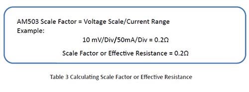
The final detail of using a current probe is to calculate the effective resistance of the probe. If you used a resistor of value R to measure current, you would get R volts across the resistor for every amp through it. The current probe has an effective resistance, which is the number of volts out of the current probe amplifier for every amp through the current probe. The Tektronix AM503 series of current probe amplifiers have a fixed output of 0.01 volts for a unit of current equal to the range setting.
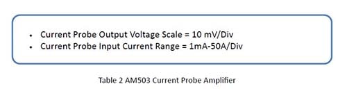
The current probe amplifier output is 0.01 volts per division and the range setting is given in amps per division so the effective resistance of the current probe is 0.01 divided by the range setting. If the amplifier is set to 10 milliamps (0.01 amps) per division, then the effective resistance is 1 ohm. One common error in making impedance measurements is to leave the current probe amplifier set to 10 milliamps per division no matter what current is being measured. This simplifies the math, since there is no need to use the Scale Factor provision of the testing and plotting software. It also means that often the current probe will be operated far from its optimum range, sometimes even in the saturation region where the output is no longer linearly proportional to the input. Failure to choose the proper range is another common source of error in impedance measurements.
The polarity of the probe also must be accounted for when determining the scale factor or effective resistance of the current measurement. The polarity of the probe is indicated by an arrow where the current is positive if it flows in the direction of the arrow. For a positive scale factor, the current probe arrow must be pointed at the terminal or port of the device whose impedance is being measured. If the arrow is pointing away then the scale factor will be negative.
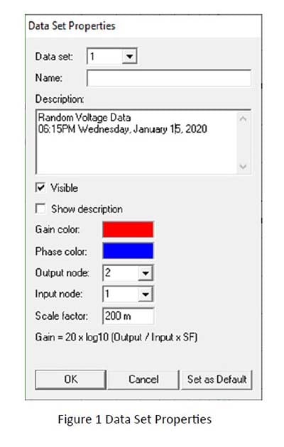
The calculated scale factor or effective resistance is entered into the Scale factor text box in the Data Set Properties window. The Data Set Properties window opens at the beginning of every sweep in version 5 and earlier Venable software. See Figure 1 below. The Data Set Properties window for version 6 Venable software is always present below the plot window and the Data Set Properties for each data set is displayed when it is selected or highlighted.
 To review, for making accurate impedance measurements with current probes, choose a reasonable current probe rating. Verify the termination is 50 Ohms or terminate the current probe, view the current and voltage wave-forms with an oscilloscope. Choose a current range that gives 3-8 divisions on scope. Adjust the DC level to zero and do not degauss probe. Determine the polarity and calculate effective impedance or scale factor of the current probe.
Read prior blog posts:
FEEDBACK LOOP INJECTION LEVELS FOR MEASURING LOOP GAIN