Why are source-load impedance measurements necessary? Distributed power systems can oscillate, especially when one or more switching power supplies are the loads of another power supply. Loads, especially switching power supplies with a high regulation bandwidth, draw constant power over the input voltage range and therefore look like an incremental negative resistance. Combining an incremental negative resistance with filters used to reduce switching noise can reduce or eliminate the damping which can cause an entire system to become unstable and oscillate. The following post will explain the basic equipment and setup to make voltage injection impedance measurements
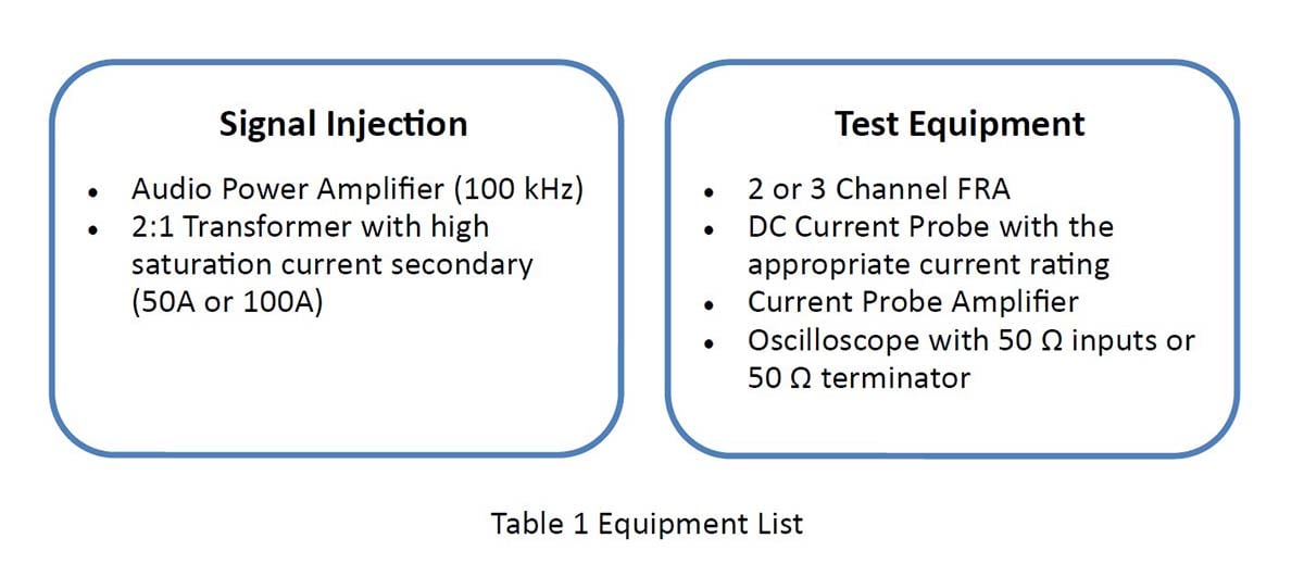
With the Input/Output Impedance (IOZ) Test Set option of the Venable Instruments System, you can measure input and output impedance of any power supply (or almost anything else for that matter). The Input/Output Impedance Test Set consists of a dc coupled high-power 4-quadrant amplifier and high saturation current secondary injection transformer. The injection transformer is capable of handling large amounts of DC current while still coupling an AC signal into the circuit. The standard power amplifier is rated 500 watts, and higher power ratings are available on special request. The injection transformer secondary is rated 50 or 100 amps DC depending on model. Because the power amplifier is 4-quadrant, this system will also work for making measurements with an AC power source instead of DC. Since AC load current is transformed by the injection transformer and has to flow through the power amplifier, check with us here at Venable Instruments before making high power AC measurements to make sure the power amplifier is not overloaded and damaged. DC measurements are safe up to the rated voltage and current of the injection transformer.
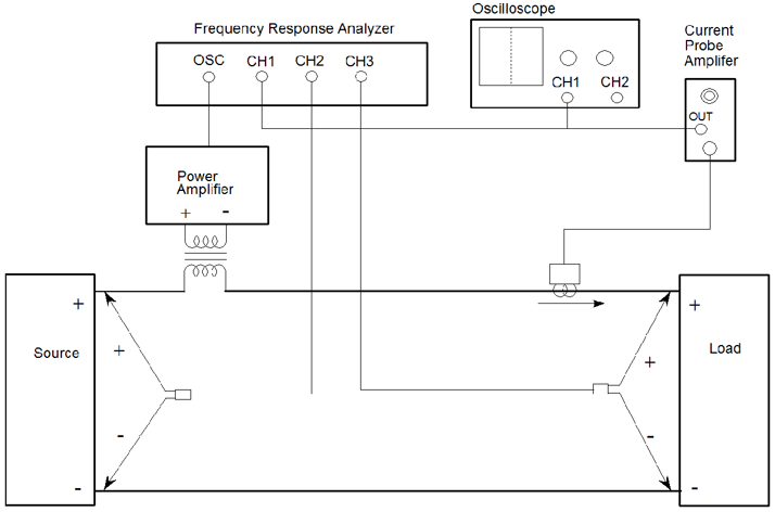
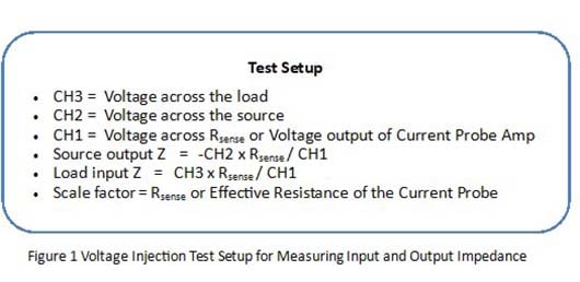
The test setup above in Figure 1 shows the setup for measuring impedance using a three channel analyzer. Whether the “Load” is the Unit Under Test, or the “Source” is the Unit Under Test, this setup will measure either Unit Under Test. Just like passive component measurements, the impedance is voltage divided by current. In the test setup shown, source output impedance is CH2/CH1 and load input impedance is CH3/CH1 noting that there may also have to be a scale factor if the output of the current probe amplifier is not 1 volt per amp. If your system does not have a channel 3, then you must move CH2 to the load side of the injection transformer to measure the input impedance of the Unit Under Test.
Current probes are directional. If the arrow on the current probe is pointing toward the load, then the measured impedance of the load will be the correct polarity. The scale factor of the data set will be the effective resistance of the current probe, which is the rated volts per division of the current probe amplifier output divided by the amps per division setting of the current probe amplifier. For measuring the output impedance of the source, if the arrow on the current probe is pointing toward the load (away from the source) then the scale factor will be the negative of the effective resistance calculated above for the load input impedance measurement. It is important to pay attention to the direction of the current probe arrow, especially if you do not have a feel for the expected phase of the test result impedance.
The current probe amplifier output will have to be terminated into 50 ohms. An inline 50 ohm terminator can be used with analyzer current measuring channel. These terminations should always be checked before use to ensure that they are not damaged and are the correct impedance. Since older current probe amplifiers need to have their DC balance adjusted manually, a better method of termination is to use an oscilloscope with the input set to 50 ohms. This method allows the DC balance to easily be adjusted to 0 VDC. Also, the DC current, injected current and voltages levels can be monitored during the test.
The analyzer channels not dedicated to measuring the current are used to measure the voltage of the “unit under test”, that is either the source or load or both in the case of a three channel analyzer. All of the two, three, and four channel models of the Venable analyzers, except the for the 5140, have a floating generator and channels rated to 600 Vpk and input range of up to 500 Vpk which will handle a wide range of measurement applications. For measuring higher voltages, 100:1 voltage probes for the channels and high voltage model of the injection transformer may be needed.
The Input/Output Impedance (IOZ) Test Set option in conjunction with a current probe and Frequency Response Analyzer (FRA) can be used to measure the input or output impedances versus frequency of switching power supplies. The amplifier and injection transformer provide the drive and isolation to disturb the power line with the analyzer oscillator. The analyzer channels along with the current probe enable the measurement of the input or output impedance of power supplies without any extra accessories at voltages of up to 500 Vpk.
Measuring the Input and Output Impedance of Power Supplies - Part 3
Read prior blog posts:
FEEDBACK LOOP INJECTION LEVELS FOR MEASURING LOOP GAIN
Determining Gain and Phase Margins on Venable Bode Plots