Measuring a Modulator Transfer Function
By Ford Mays - August 20, 2024
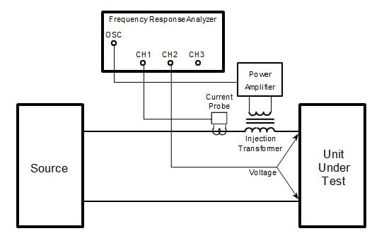
Venable’s Software Manual details many applications and procedures, and in this Application Note (excerpted from the Manual) details measuring the Modulator (plant) Transfer Function with a Frequency Response Analyzer, In previous blog articles, we have discussed the need for measuring or characterizing the ‘modulator’ or ‘plant’
- Why Does My Bode Plot Look Like That?!?
- Measure and Know Your Plant - Tuttle's Topics #2
Understanding the nature of the modulator is key in designing the proper compensation to achieve the desired overall loop gain (crossover frequency, phase margin and gain margin) for optimal power supply performance. This application note details two methods for using your Frequency Response Analyzer to measure the transfer function (gain and phase) of the modulator. Instructions for performing either the ‘open loop’ or ‘closed loop’ are detailed in the application note. Once the modulator is understood, designing the feedback circuit is made easy with Venable’s Stability Analysis Software tool, Circuit Analysis.


