The concept of negative resistance is very real, and the consequences of certain unintended occurrences must be examined and accounted for. Negative resistance occurs when the “Volts per Amp” (V/I) has a negative sign, which implies that the circuit element(s) in question source power. Stated another way, a negative resistance will have a current that is 180˚ from a positive resistance. In the AC domain, passive devices that store energy (capacitors and inductors) can return stored energy to the circuit. This is useful for tuned circuits, such as the tank circuit in a Class C amplifier. We shall see shortly that negative resistance is real, due to the imaginary (reactive) component of complex impedances.
In the case of power systems, design engineers need to be aware of source and load impedances, so that undesired interactions (oscillations, big ones!) don’t occur. An inductive impedance, for example, can be plotted on a polar impedance graph, as shown in Figure 1, at a given frequency.
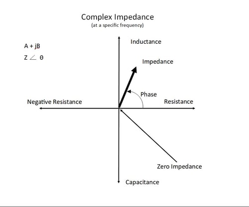
Figure 1: Complex Impedance
We can create a “negative inductive” impedance (a capacitance) with equal magnitude that is 180˚ out of phase with our inductive impedance. In our example, let us consider the inductive impedance our source impedance ZS and the capacitive impedance (negative inductance) our load impedance, ZL. At a certain frequency, the impedances are out of phase by 180˚, and if the magnitude of each impedance is equal, we have met the criteria for oscillation, as shown in Figure 2.
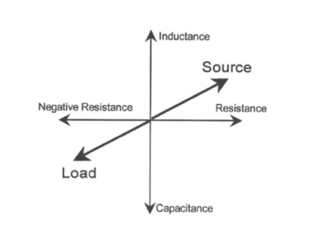 Figure 2: Criteria for Oscillation
If the sum of ZS and ZL is zero, the overall impedance is zero, which implies infinite current will flow. As noise is always present in “real life” circuits, oscillation will be triggered at the frequency where ZS=-ZL.
As an example, consider the case of a switching power supply’s input impedance (the load) and the power supply’s input filter output impedance (the source). The power supply acts as a constant power device, so as the input voltage varies, the input current varies inversely. Such behavior is an incremental negative resistance, and oscillations can result unless we ensure that the load impedance is greater than the source impedance across frequency.
The importance of understanding system impedances cannot be understated, especially given the realm of distributed power in mission critical or large enterprise systems. In such systems, additional filters (EMI/RFI) between the source(s) and load(s) tend to result in more complicated reactive interactions that must be characterized and accounted for.
Frequency Response Analyzers (FRAs) are very well suited to measuring input and output impedances, providing easy to read, graphical results.
For more information on this subject, please download the white paper “Distributed Power: What Causes These Systems To Oscillate”.
Additional Blog Content:
Protect your Distributed Power System from Oscillation
Why Conditionally Stable Systems do not Oscillate
Measuring the Input and Output of Impedance of Power Supplies