This is the third installment of a multi-part series of blogs that discusses feedback loop control design concepts, analytical methods and tradeoffs. Although we will use power supply examples, the concepts (as Dean Venable oft reminds us) apply to all servo loops. We will do this with a minimum of math, and focus on developing an intuitive understanding of system behavior. In this installment, we examine the closed loop performance, and how it manifests itself in the time and frequency domains. To effectively close the loop, certain design specifications (crossover frequency and phase margin) are critical to success.
“Closing the Loop-Crossover Frequency”
In the first installment, we discussed two graphical analytical methods, the transient response and the frequency response, and how the two methods show us how and why the system responds the way it does. In this installment, we will examine the closed loop performance and how the choice of crossover frequency manifests itself.
From the previous discussion, we used a simple buck regulator without any feedback. The regulator schematic is shown in Figure 1.
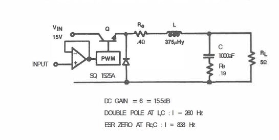
Figure 1. Buck regulator example (voltage control mode, continuous inductor current).
Now we are going to take a bit of a “black box” approach to compensation for the sake of this discussion. This means that we are closing the loop, providing feedback from the output of the modulator to the error amp controlling the PWM. The feedback circuit (compensation) has its own poles and zeroes that are combined with the poles and zeroes of the modulator (plant) to provide the overall system transfer function (often referred to as “loop gain”).
The loop gain has the characteristics of gain and phase when presented in the frequency domain (graphically as a Bode plot). The important aspects of this method of evaluating performance are crossover frequency and phase margin. For our discussion, we are going to examine the nature of crossover frequency (this is not to say that phase margin is not important, because IT IS!).
How does the loop gain crossover frequency affect performance? What does it look like in the time domain?
Below are two graphs of the transient response of the closed loop performance of our buck regulator. Both have the same phase margin (60 degrees), but different crossover frequencies.
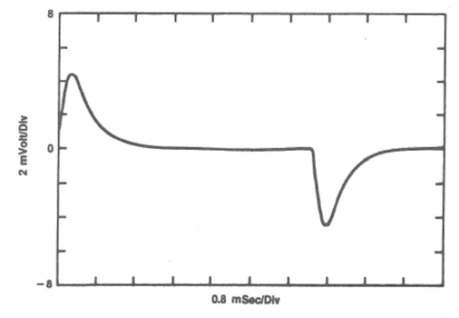
Figure 2. Transient Response, 2.5kHz Crossover Frequency
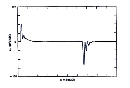
Figure 3. Transient Response, 250Hz Crossover Frequency
So, what gives? Why is the transient so much larger in Figure 3? Why is it ringing?
As noted in Figure 1, the output filter inductor and capacitor form a series resonant circuit, where the resonant frequency is 260Hz, and we see the output filter ringing in Figure 3. In Figure 3, the crossover frequency is below the output filter’s resonant frequency. This means that the feedback circuit cannot eliminate or control the ringing. In Figure 2, the crossover frequency is 2.5kHz and well above the output filter’s resonant frequency. The ringing is eliminated and the transient response is muted.
The frequency domain representation of gain and phase (Bode plots) of the two different loop gains are shown below, Figures 4 and 5. As one can see, the crossover frequency for the compensated plant transfer function (loop gain), is easily read.
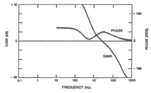
Figure 4. Bode Plot, 2.5kHz Crossover, 60 Degrees Phase Margin
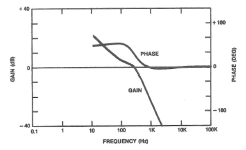
Figure 5. Bode Plot, 250Hz Crossover, 60 Degrees Phase Margin
By making the loop gain’s crossover as high as practical we can control transients of higher frequencies, but is there an upper limit to crossover frequency? Yes, there is. As we increase the crossover and maintain constant phase margin, the low frequency gain suffers, resulting in slower low frequency transient response (please see IMPORTANT POINT #1 of “Relating Converter Transient Response Characteristics to Feedback Loop Control Design”), In the case of switching power supplies it is desirable to keep the crossover frequency of the loop gain below the switching frequency (usually a decade below). We want the feedback circuit to reject the switching noise, otherwise switching noise is treated as a transient and the closed loop performance suffers (technically, it goes to “hell in a handbag”).
In the next installment, we will pick up with our example and determine the compensation needed and the effect that phase margin can have on transient performance. If you cannot wait for the next installment, please read Wayne Tuttle’s paper "Relating Converter Transient Response Characteristics to Feedback Loop Control Design".
Tuttle Topic 2 - Measure and Know Your Plant