In the previous blog post, Feedback Loop Injection Levels for Measuring Loop Gain, we talked about how to manually set the correct amount of injection voltage into a feedback loop in order to get an accurate and noise free plot.
This blog post will show how to set the correct amount of injection voltage into a feedback loop using the Servo function in the Analyzer Control menu.
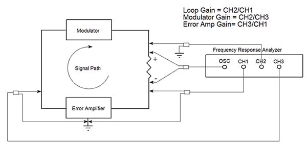 Figure 1 Injection Method for a Floating Generator
To review, the best way to set the injection level into the feedback loop is to look at the measured voltage level of channel 2 on the output of the loop gain. The best point to do this is at the start frequency if you are sweeping upwards from high gains and lower frequencies. Assume that Ch.2 is measuring the output of the loop gain and Ch.1 is measuring its input. Typically, at low frequencies and higher gains channel 1 voltage will be very small, in the microvolts range, and the channel 2 voltage will be much larger, typically in the tens of millivolts. Refer to figure 2. With a constant injection voltage level, the generator or V3, channel 2 or V2 and channel 1 or V1 form a vector triangle. At crossover frequency, they form an isosceles triangle where V1 = V2 and the difference in the phase between them is the phase margin. At low frequencies and high gain, V1 is very small, perhaps, as much as 1000 times smaller than V2 and therefore, V2 ≈ V3. Channel 2 is essentially equal to the injection voltage and can be used to set the injection level into the feedback loop.
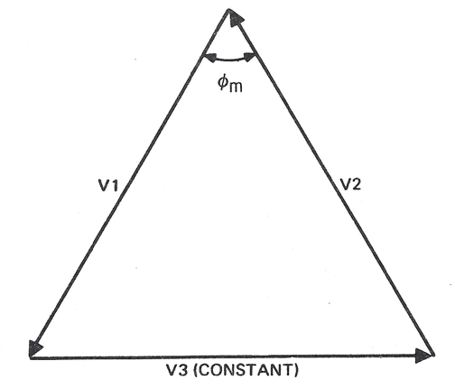
Figure 2 Vector Triangle
The easiest way to set the injection level instead of doing it manually is to use the servo function on the Analyzer Control menu to set the voltage on channel 2 to a certain level. When the servo is enabled the generator output will be varied to maintain the voltage set on the channel 2. See figure 3. Turn on the servo, by checking the Servo On check box. Set the channel to CH 2. A good level to start is AC Volt In = 20 mV. The AC Out Step Size control sets the maximum step that servo will take when adjusting the output voltage. The default value is 10 dB. The Max AC Volts Out control limits output voltage level of the generator. The default is set to 10 V. It can be used to limit the maximum generator voltage level that can be injected into the circuit. This is a useful feature if there is faulty channel connection or disconnected cable. In that case, the generator output will increase until it reaches the limit set in Max AC Volts Out trying to maintain the channel 2 voltage at the value set in AC Volt In control.
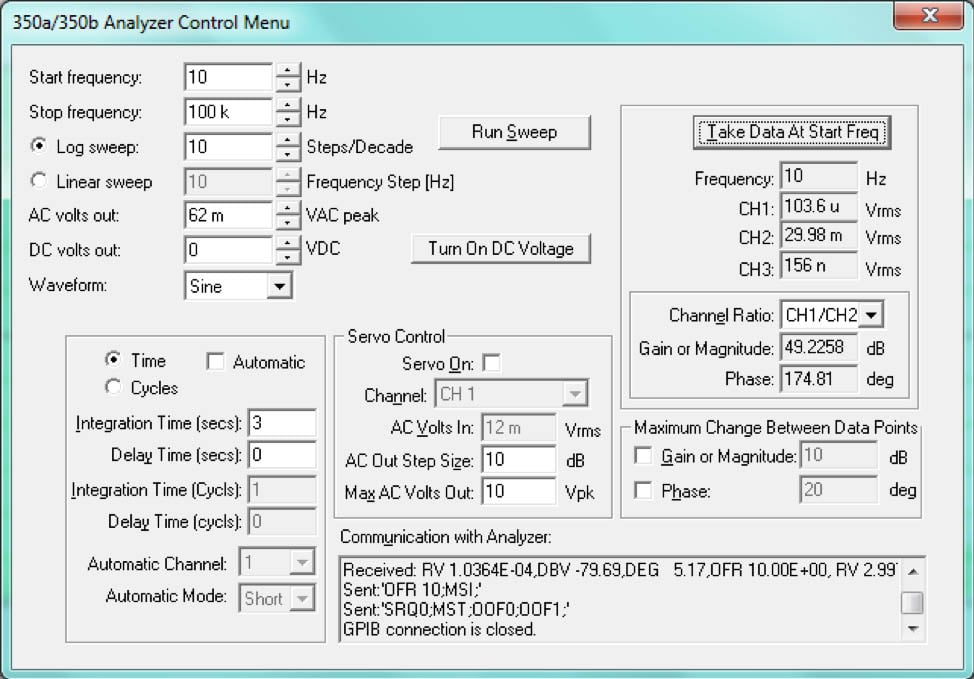
Figure 3 Analyzer Control Menu Servo Settings
The Take Data at Start Frequency button can be used to check the channel 2 reading or injection level before starting the sweep. Click on the Take Data at Start Frequency button. The servo will start at the lowest generator setting, typically either at 1mV or 10 mV, depending on the model and adjust upwards in 10 dB steps with each measurement until channel 2 is equal to 30 mV. The channel 2 reading, as well as, the gain and phase readings should be stable before starting a sweep. They should not move much. The integration time and/or the injection level can be increased to stabilize the reading. In the case of the servo control, increasing the AC Volt In setting will increase the injection level.
Click on the Run Sweep button to start the sweep. The generator injection voltage will automatically adjust to maintain channel 2 at the AC Volts In control setting as the sweep progresses towards the unity gain crossover and as the gain decreases. . Once the gain has been reduced at higher frequencies, voltage injection levels can be reduced as channel 1 rises farther above the noise floor by decreasing the AC Volt In setting. This helps reduce the chance that any errors are introduced into the measurement by high injection levels at higher frequencies. There is also better noise rejection at higher frequencies because more data is processed by the DFT. Turn off the servo by unchecking the Servo On check box before or at the crossover point and let the sweep run to the Stop Frequency. The injection level will be lowest before or at the crossover where channel 1 and channel 2 are equal in magnitude depending on the phase margin. Turning the servo off keeps the injection magnitude from increasing to the level set in the Max AC Volts Out control at higher frequencies where the channel voltage 2 voltage begins to roll off.
The servo control on the Analyzer Control menu can be used to set the correct injection level into the loop automatically at the low frequency and high gain portion of the loop gain. Always try to minimize the injection level as much as possible and still get a good smooth noise free plot when using the servo control. This will minimize the chance of introducing nonlinearities that can cause errors in the measurement.
Read related content:
FEEDBACK LOOP INJECTION LEVELS FOR MEASURING LOOP GAIN
Determining Gain and Phase Margins on Venable Bode Plots