Injection Signal Location and Levels in Loop Gain Measurements
By Ford Mays - November 04, 2022
When using a Venable Frequency Response Analyzer to make loop gain measurements, there are two questions most commonly encountered by users: injection signal location and injection signal level. The primary reason that these two questions are frequently encountered is that each situation somewhat unique. Almost every application (usually a power supply, but it can be any servo loop) is defined by system requirements, so choosing the best error signal injection location in the loop and the appropriate error signal level will be different and is a bit of an art. This blog will point out the guideposts to finding the best answers to error signal injection location and level.
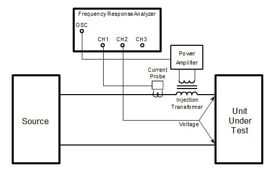
Choosing the point where the injection resistor is inserted for a closed loop gain measurement has a couple of rules of thumb, the loop has to be confined to a single path and a low impedance is driving into a high impedance. TIP - This injection point is typically at the top of the resistor divider string (that scales the feedback voltage) where it connects to the output of the power supply. Frequency response analysis is a small signal measurement, so it might be useful to think of the voltages on each side of the injection resistor as Vout and Vin. So, the voltage on the side of the resistor looking back into the modulator (plant) is Vout, and the voltage on the other side of the resistor looking in to the feedback circuit (compensation) is Vin. Thusly, the gain (and phase) is found on each side of the injection resistor, i.e.:

To accurately measure the gain and phase of the loop, we want to use the smallest error signal level that yields a smooth plot. If you start your sweep at low frequency, Vout or channel 2 should be on the order of tens of millivolts, and Vin or channel 1 on the order of tens of microvolts. The oscillator or generator should be set between 10 mV to 100 mV to start. TIP - Use the Take Data at Start Frequency button in the Venable software to adjust the oscillator output level to get a steady gain and phase reading before starting the sweep. At low frequency, the loop gain is large, and it decreases as frequency increases. If left alone during the sweep, Vout decreases and Vin increases as frequency increases. This may or may not be a problem, but if it is, the Servo function in the Venable software can be used to eliminate it. The Servo function will adjust the error signal (generator output) level to maintain a constant input level to the selected channel. The Servo function should not be used past the crossover frequency, since the loop gain is less than one (it can be turned off during the sweep or “on the fly”). A helpful video on this is found here: How to Use the Servo Function.
With this understanding of the error signal injection site selection and levels, any Venable Frequency Response Analyzer user can be successful making loop gain measurements of any servo loop. However, if one has questions, we are always happy to answer them, reach out support@venableinstruments.com


