When making input or output impedance measurements using a Frequency Response Analyzer, one injects a small AC signal onto the power bus, and the necessary AC voltage(s) and current(s) are measured. The current measurement is translated to a voltage for the FRA to measure, and the impedance is calculated. There are two ways to inject the AC disturbance, Voltage Injection and Current Injection. Each is depicted below in Figure 1.
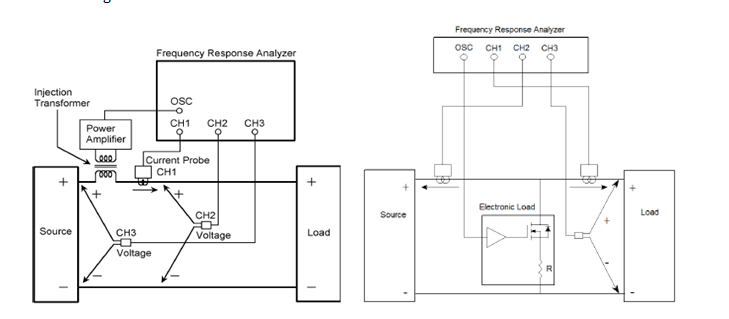
Figure 1. Voltage Injection (left) and Current Injection (right)
As you can see in the diagram, the Voltage Injection method uses a transformer and low output impedance amplifier to impress the AC signal onto the bus. With Current Injection, an electronic load is used to modulate the bus current. Both methods result in an AC disturbance that allows one to measure the source or load impedance. As a rule of thumb, a ten percent (10%) modulation of the load current is a good starting point for impedance measurements.
The Venable IOZ Measurement kit supports the 'Voltage Injection' methodology. This method was selected as it is valid for as many possible measurement conditions (bus voltages and currents) with a minimum of different test equipments.
To use the Current Injection Method, there are a few 'off the shelf' electronic loads that can be modulated, but what some may find more suitable for their requirement is a custom load circuit. An 'off the shelf' electronic load (that can be modulated) may not have the bandwidth necessary for you to completely characterize the impedance you want to measure. On the other hand, a 'home brew' load will have the voltage rating, current capacity, and bandwidth that will suit your needs.
To create your custom electronic load, you will need a MOSFET or IGBT of suitable voltage, current, and bandwidth, a non-inductive resistance and a heat sink on which to mount them. The oscillator output of the Venable FRA can source the AC with a DC offset. The DC offset can be used to place the transistor near or in the active region. The resistive load should be sized to carry the necessary current. You can modulate the transistor with a square wave (up to 1MHz) or a sine wave (up to the FRA's maximum frequency). The FRA will filter out the harmonics of a square wave (but you may have to increase the integration cycles/time). The benefit of current injection is that it can be 'scaled' to the particular application, does not require anything to be placed in series, and has much greater bandwidth.
The Venable IOZ Measurement kit is suited for most source or load impedance measurement applications as it is Voltage Injection based. Current Injection requires an electronic load that can be modulated, which may require a custom load circuit. For more information on Venable Instruments’ products to meet your testing needs feel free to reach out via email or 512-949-3141.
Related Content
Measuring the Input and Output of Power Supplies (Part 1)
Measuring the Impedance of Power Supplies - Current Probe and Scale Factor (Part 2)
Measuring the Input and Output Impedance of Power Supplies (Part 3)