Voltage Injection Scalability for High Current Impedance Measurements
By Ford Mays - November 12, 2024
When making input/output (source/load) impedance measurements using the voltage injection method, the bus current may exceed the capability of a single injection transformer. In this article, we will discuss the ability to parallel the secondaries of multiple injection transformers to increase the current capacity of the voltage injection measurement method and drive them with a single amplifier.
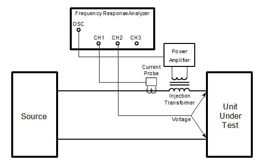
Venable’s Input/Output Impedance Measurement Kit consists of a high saturation current secondary injection transformer(s) and a DC coupled 4-quadrant power amplifier. The primary purpose of the test set up is to provide enough drive for the FRA generator and amplifier to inject a disturbance into the power bus and measure the input or output impedance of the source or load (or both). This setup is depicted below as a single injection transformer configuration.
Figure 1. Single Injection Transformer Voltage Injection Test Setup for Measuring Input and Output Impedance
The injection transformer is capable of handling large amounts of DC current while still coupling an AC signal into the circuit. The injection transformer secondary is rated to 100 amps DC which may not be adequate for large busses found in data center (for example) power distribution systems. For current levels higher than the individual transformer secondary ratings, the secondaries of two or more injection transformers can be connected in parallel to increase the rated current through the secondary. The primary side can be connected in parallel or in series as shown in Figure 2a and 2b, respectively.

Figure 2a. Parallel Primary Injection Transformer Connections

Figure 2b. Series Primary Injection Transformer Connections
It is worthwhile to note that the Venable 100A injection transformer is a step-down transformer with a 2:1 turns ratio. In the configuration shown in Figure 2a, the primaries are connected in parallel, as are the secondaries, and the net step-down turns ratio remains 2:1. However, when the primaries are connected in series and the secondaries in parallel (Figure 2b), the net step-down ratio changes. They are listed in Table 1 below (up to six transformers).
%20Turns%20Ratio.jpg?width=577&height=307&name=Table%201.%20Effective%20(Net)%20Turns%20Ratio.jpg) Table 1. Effective (Net) Turns Ratio
Table 1. Effective (Net) Turns Ratio
Impedance measurements are small signal measurements. It is good practice to minimize the injection level as much as possible and still get a smooth, noise free data plot. There are three ways to reduce noise, one is to increase injection level to the transformer primary (either at the FRA output or at amplifier output), another is to increase the integration time or cycles, and the final way is to increase both. An increase in the injection level will move the smallest channel measurement away from the noise floor. Of course, there is a practical limit to how much signal can be injected. It is a good idea to monitor the AC injection level with an oscilloscope, especially at frequencies below 30 Hz, to avoid saturating the injection transformer(s).
Venable Instruments has many years of experience measuring source and load impedances and providing integrated solutions. Venable’s Frequency Response Analyzers and Input/Output Impedance Measurement Kits provide superior results. The voltage injection method provides a flexible and scalable solution to source/load impedance measurements.
For details on how to make source and load impedance measurements, Venable has a three-part series of blogs that detail the equipment needed, test set up, and procedures. The articles are found here:
Measuring the Input and Output Impedance of Power Supplies (Part 1)
Measuring Impedance of Power Suppliers - Current Probe and Scale Factor (Part 2)
Measuring the Input and Output Impedance of Power Supplies (Part 3)


