Analysis of the stability of feedback loops has always been a subject that was shrouded in mystery and confusion. Recent efforts to clear away some of these problems have helped, but even with computer-aided
design, a certain amount of trial-and-error remained. This paper presents a new mathematical concept that is simple but powerful. The techniques described allow synthesis of a feedback amplifier with a few algebraic equations to obtain any desired crossover frequency and phase margin (within reason) on the first try.
Reprinted from the Proceedings of Powercon 10
H. Dean Venable
(C)Power Concepts, Inc. 1983
1. INTRODUCTION
Stability analysis of feedback loops has historically required a certain amount of trial-and-error. Computer modeling and computer-aided design allowed one to evaluate results of a particular design with relative ease, but it was still difficult to start with a desired result and then determine the exact circuit values required to obtain that result. This paper presents three standardized feedback amplifiers which cover the requirements for every known loop. These amplifiers, together with a new mathematical concept called the K Factor, allow the circuit designer to choose a desired result, i.e., a particular loop cross-over frequency and phase margin, and then determine the necessary component values to achieve these results from a few straight-forward algebraic equations.
2. THE NATURE OF LOOPS
A typical loop is shown in Figure 1. The loop consists of a power-processing block called a MODULATOR in series with an error-detecting block called an AMPLIFIER.
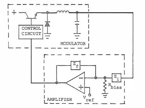
The modulator can be as simple as the buck regulator shown, or it could have been a complex hydraulic servo system or an aircraft attitude control system. No matter how complicated the modulator, the principle is the same: a portion of the output is compared to a reference in an error amplifier, and the difference is amplified and inverted and used as a control input for the modulator to keep the controlled variable constant. Even in multiple-loop systems, there is still one main loop that performs this function.