Reprinted from the Proceeding of Powercon 7
H. Dean Venable and Stephen R. Foster
Hughes Aircraft Company
Torrance, California
Abstract
Practical techniques are shown for analyzing the response of switching regulators and determining and realizing the desired feedback characteristics to achieve stable closed-loop operation. These techniques employ reactance paper to reduce the calculation time to minutes and increase understanding of circuit behavior. Measurement techniques are also shown which allow loop gain and phase margin to be determined in a few seconds while the circuit is operating.
1. INTRODUCTION
Many papers have been written in recent years concerning detailed mathematical analysis of the closed-loop frequency response of switching regulators. The value of these papers is without doubt, and a number of them are referenced herein. The purpose of this paper, however, is to take a step backward in complexity, and a step forward in understanding stability analysis.
2. THE BASICS
2.1 TRANSFER FUNCTIONS
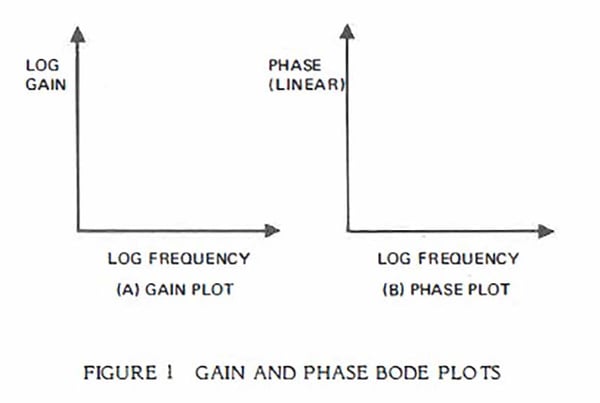
The transfer function of a circuit is simply the output divided by the input. This function has a gain and a phase component and is usually a function of frequency. The most useful form of the transfer function is the Bode plot, named after H. W. Bode of Bell Telephone Laboratories. Typically there are two Bode plots required, gain and phase. The use of log scales greatly simplifies graphical analysis (see Figure l ).
The gain and phase shift around the loop of a closed-loop system is simply the product of the gains of all elements and the sum of the phase shifts of all elements. When the gains are plotted logarithmically, the product can be determined graphically just by summing the gain of each element. Typically in a switching regulator, there are only two elements to sum. One is the modulator, the device which takes a control voltage and causes the input power to be chopped and then smoothed to provide a d.c. output voltage, and the other is the feedback amplifier which senses the d.c. output voltage, compares it to a reference, and outputs a control voltage to the modulator.
2.2 POLES
Technically, poles are points on the s-plane where the denominator of the transfer function goes to zero. Realistically, they are points in frequency where the slope of the Bode gain plot breaks downward.
A very important point to know and remember is that in linear circuit analysis, the Bode plot can have only a limited number of discrete slopes and phase shifts except in a transition region near poles and zeros. (See Table I)
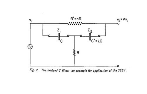
The "Phase Shift per Decade" column is the approximate slope of the phase curve near poles and zeros. A pole causes a transition from a +I to a O slope, or O to -1, or -1 to -2, etc. This is accompanied by a 90° lag in phase shift. Some circuits which cause poles and their respective Bode plots are shown in Figure 2.
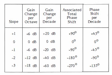 Table 1. Some Allowable Slopes and Phase Shifts on a Bode Plot
2.3 ZEROS
Zeros are points on the s-plane where the numerator of the transfer function goes to zero. Practically speaking, they are points in frequency where the slope of the Bode gain plot breaks upward. A zero causes a transition from a -I to a O slope, or -2 to -1, or -3 to -2 etc. This is usually accompanied by a 90° lead in phase shift. Because of the nature of boost and buck-boost regulators, however, a right-half plane zero usually occurs in the transfer function of the modulator portion. A right-half plane zero causes the Bode gain plot to break upward the same as a left-half plane zero, but is accompanied by a 90° phase lag instead of lead. This phenomenon necessitates more care in the stabilization of boost and buck-boost regulators than in buck regulators, so that loop gain crossover occurs well below the frequency of the right-half plane zero. Circuits causing both poles and zeros are shown in Figure 3.
Figure 4 shows the difference between a left- and a right-half plane zero.
2.4 STABILITY CRITERIA
How do you make an oscillator? Simple! Just make a closed loop feedback control system that still has more than unity (0 dB) gain when the total phase shift around the loop is 360 degrees. Conversely, to make a system stable, make sure that the loop gain has fallen below unity by the time the total phase shift has reached 360°. The amount the gain is below unity when the total phase shift is 360° is called the gain margin. The closely related criterion, phase margin, is the difference between the actual phase shift and 360° when the loop gain is unity.
Most feedback control system texts talk about stability in terms of 180° of phase shift. This is because at d.c. the feedback is negative, that is, there is 180° of phase shift to start with. The stability criteria are then based on an additional 180° of phase shift.
Notice in Table I that in order for the gain to fall off with increasing frequency, a minimum of 90° of phase shift is required. This 90° is in addition to the 180° at d.c., so that a system with a single pole rolloff (-1 slope) at crossover will have 270° of total phase shift or a phase margin of 90°. Notice also that a system with a two pole rolloff (-2 slope) will have 360° of total phase shift and be on the verge of oscillation, if it does not in fact oscillate.
Notice especially in Table I that a system with a three pole rolloff (-3 slope) will have a whopping 450° of total phase shift and is sure to oscillate! The reason that this is important to note is that switching regulators inherently have three pole rolloff in the closed loop feedback mode, 2 poles from the modulator and one additional pole from the feedback amplifier. A principal objective of this paper is to present techniques for achieving stability by reducing the closed loop gain rolloff rate to a -1 slope in the region of gain crossover (unity gain).
3. SWITCHING REGULATORS
All switching regulators operate on the principle of storing energy in an inductor on one portion of a cycle and then transferring the stored inductive energy to a capacitor in another portion of a cycle. The buck converter, shown in Figure 5, is the simplest example.
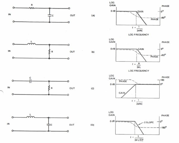 Figure 2. Circuits which cause Poles