Welcome to the first installment of Venable Instruments’ “Did You Know….” series of blogs that focus on tips, insights, hints and tricks in using the Venable Stability Analysis System. We will focus on instrument, software and measurement features and insights that we hope will make your tasks easier. In this installment, we will discuss error signal injection level changes made “on the fly”.
In the past we have discussed getting the appropriate injection levels (Injection Signal Location and Levels in Loop Gain Measurements) and using the Servo Function (Using the Servo to Set Feedback Loop Injection Levels for Measuring Loop Gain). Additionally, there is a video available on how to use the Servo Function.
What many users don’t realize, is that the injection level can be changed during a sweep without having to stop and restart the sweep. During a sweep, the user can change the injection level (‘AC Volts Out’ in the Analyzer Control Panel, Figure 1).
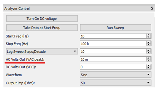
Figure 1. AC Volts Out in the Analyzer Control Window
The change will take effect at the next frequency point measured. The ‘DC Volts Out’ can be changed on the fly as well (if one needs a DC bias on the generator output). If the user has the Servo Function enabled, the injection level can be manipulated indirectly by changing the ‘AC Volts In’ in the Servo On section of the Analyzer Control Panel (Figure 2).
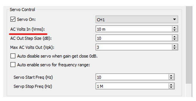 Figure 2. AC Volts in the Servo Control
Generally, one might want to reduce the injection level as the sweep frequency increases, since the overall loop gain is decreasing. There may be noise sources (intrinsic to the circuit being tested, or external) that require an increase in injection level during the sweep.
There are other parameters that can be changed during the measurement sweep, such as the stop frequency, integration time/cycles and more. Venable Instruments has done this to make taking measurements easier and more productive. If you have any questions about the Venable Stability Analysis Software, please let me know.
Related Content Posts
New Signal Injection Technique Simplifies Power Supply Feedback Loop Measurement
When to Use a Bode Box Injection/Isolation Transformer
Feedback Loop Injection Levels for Measuring Loop Gain