The Venable Advantage
By Ford Mays - April 18, 2024
At Venable, our team focuses on delivering high quality test instrumentation that supports ease of use, accuracy, with the best technical support available. Venable has a cumulative 80+ years of experience of power supply design and testing.
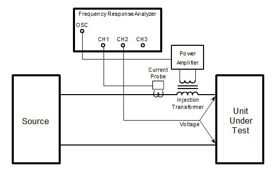
Venable's Frequency Response Analyzers have isolated (floating) channel inputs and oscillator output. The channel inputs and oscillator output are rated to 600Vpk (common mode), and the channel inputs are rated at 500V (differential). This eliminates the need for voltage reduction probes and injection transformers. By eliminating the injection transformer, the user has the entire bandwidth of the FRA available for measurements. Additionally, you don't have to buy and keep up with additional accessories (connections to the circuit under test are made directly to the Venable FRA).
Venable's FRAs are based on a common, modular architecture. This means that an existing customer can upgrade their instrument in bandwidth, number of channels or both. The cost to do this is comparable to the difference in cost of the original model and the end model (plus a calibration). In this fashion, your instrument is 'future proofed' as test requirements change. Additional bandwidth is always useful when making impedance measurements of components (RLC measurements). A commonly added channel is the digital channel, which is used when working with digitally compensated power supplies.
Our Stability Analysis Software not only controls the instrument during measurements, but is also a development tool. One can synthesize a feedback circuit with a specific crossover frequency and phase margin and simulate it. By combining the simulated feedback circuit and measured modulator mathematically, one can see that the loop gain has the desired crossover and phase margin (this works with digitally compensated loops as well). This saves a great amount of time.
Venable's FRA measurement algorithm yields better, noise free results. Our DFT filtering can be set (for all points in a sweep) from 0.02 seconds to 100,000 seconds (1 to 100 cycles), resulting in a filtered DFT bandwidth of 10uHz to 50mHz. Additionally, our two stage receiver architecture has a dynamic range of >120dB. Venable performs these measurements in one sweep, we do not average multiple sweeps. We can dig measurements of a few micro-volts out of the noise.
One last point is tech support. The Venable team is located in Austin, Texas and is always available to help. Customers get to connect with the Engineers that designed the hardware, wrote the firmware and software and developed measurement techniques. When time is of the essence, we are there to make you successful.
Please contact us here or call (512-949-3144) or email (dwoodard@venableinstruments.com) me for assistance.
Top Blog Content
Measuring the Open Loop Gain of an Operational Amplifier
Determining Gain and Phase Margins on Venable Bode Plots
Why Conditionally Stable Systems Do Not Oscillate
Negative Resistance: Real or Imaginary
Measuring the Input and Output Impedance of Power Supplies (Part 1)


